AG900+ and AG900+S Applicators Customer Product Manual.pdf - 第18页
AG − 900+ and AG900+S Applicators 14 Part 1098464A 2009 Nordson Corporation Physical Dimensions (contd) T o install the AG-900+/AG900+S applicator , perform the following procedures: 1. See Figures 3 and . Remove the M…
AG−900+ and AG900+S Applicators
13
2009 Nordson Corporation
Part 1098464A
Installation
WARNING! Allow only personnel with appropriate training and
experience to operate or service the equipment. The use of
untrained or inexperienced personnel to operate or service the
equipment can result in injury, including death, to themselves and
others, and damage to the equipment.
The AG-900+/AG900+Smodular dispensing applicator is shipped fully assembled.
After unpacking:
1. Inspect the applicator assembly for dents, scratches, corrosion or other physical damage.
2. Heated units: inspect the cordset assemblies for damaged or bent pins or kinking in the
armor shielding.
3. Tighten and secure all fasteners.
Contact Nordson immediately to report damaged or missing items.
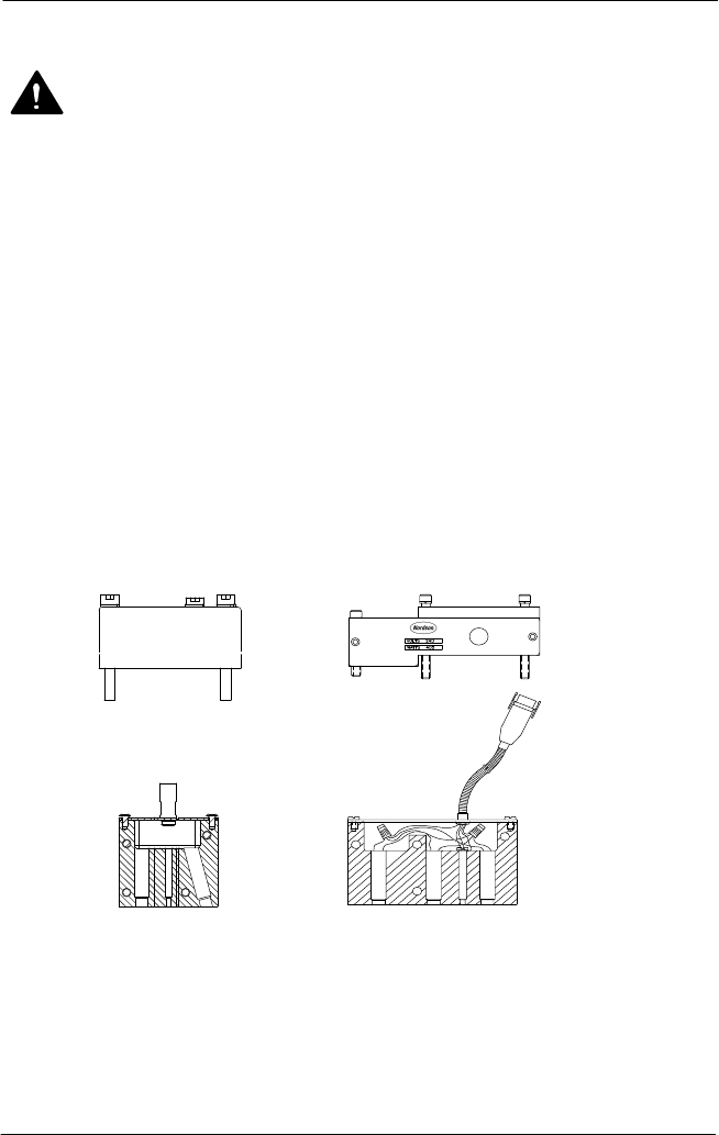
See Figure 2.The AG-900+/AG900+S applicator is mounted on a bracket, supplied by the
customer, that is secured to the applicator regulator module by using three M5 socket head
screws.
12
3
4
Figure 2: Socket Screws for Bracket Mounting with Adapter Block and Regulator
Heaters
1. Applicator bracket
2. Mounting bracket for heated regulator
3. Heater assembly for adapter block
4. Heater assembly for regulator
AG−900+ and AG900+S Applicators
14
Part 1098464A
2009 Nordson Corporation
Physical Dimensions (contd)
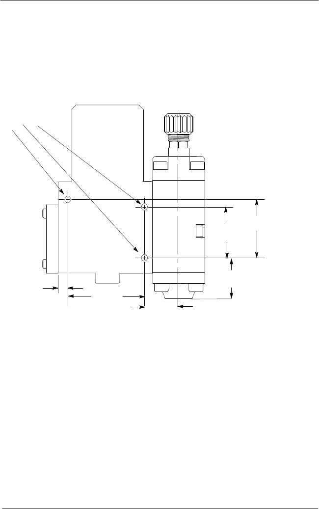
To install the AG-900+/AG900+S applicator, perform the following procedures:
1. See Figures 3 and . Remove the M5 mounting screws.
NOTE: On heated applicators, these screws also secure the heater assembly module
to the applicator.
38.7 mm
(1.525 in.)33 mm
(1.3 in.)
54.4 mm
(2.14 in.)
7.2 mm
(0.285 in.)
M5 Screw
24.1 mm
(.95 in.)
(1.1 in.)
28 mm
Figure 3: Mounting Dimensions for AG-900+/AG900+S Applicator with Regulator
AG−900+ and AG900+S Applicators
15
2009 Nordson Corporation
Part 1098464A
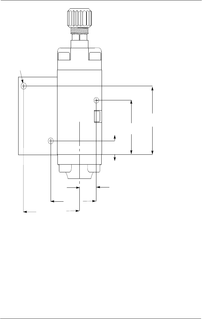
M5 Screw (X3)
48.25 mm
(1.90 in.)
42.67 mm
(1.68 in.)
9.65 mm
(.38 in.)
14 mm
(.55 in.)
39.88 mm
(1.57 in.)
54.36 mm
(2.14 in.)
Figure 4: Mounting Dimensions for AG-900+/AG900+S Applicator with Adapter Block
2. Position the applicator assembly against the customer-supplied bracket, and then
reinstall the three M5 screws and tighten securely.
3. Remove the steel hex cap from the
1
/
8
NPT port in the applicator body, and then thread
an air supply line to the port. Use PTFE tape or an equivalent on the air supply line.
4. See Figure 5. Thread a muffler to the air-close port.
NOTE: Order part number 1096469 solenoid assembly with tubing to use air-close.
5. Connect the air line(s) to an independently regulated, filtered, unlubricated and controlled
air supply.
6. For heated applicators only: connect the male plugs from the heater block adapter to the
female accessory connectors located on the heated hose or extension cords.