AG900+ and AG900+S Applicators Customer Product Manual.pdf - 第26页
AG − 900+ and AG900+S Applicators 22 Part 1098464A 2009 Nordson Corporation Disassembly (contd) 4. Remove the existing nozzle from the AG900+/AG900+S module by removing the 4 socket head screws (1) from the nozzle flan…
AG−900+ and AG900+S Applicators
21
2009 Nordson Corporation
Part 1098464A
2
3
9
4
6
8
5
1
1
7
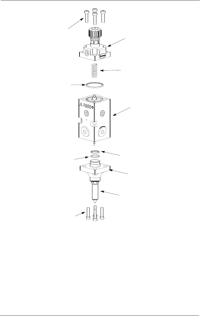
Figure 7: AG-900+/AG900+S Applicator Assembly
1. Socket head screws
2. Air cap
3. Spring
4. Module body with piston/cartridge and needle
assemblies installed
5. O-ring
6. Nozzle flange
7. Nozzle
8. Back-up ring
9. Large o-ring (top of
piston/cartridge assembly)
3. See Figure 7.Remove the four socket head screws (1), from the air cap (2) and then lift
the cap and spring (3) free of the applicator module.
AG−900+ and AG900+S Applicators
22
Part 1098464A
2009 Nordson Corporation
Disassembly (contd)
4. Remove the existing nozzle from the AG900+/AG900+S module by removing the 4
socket head screws (1) from the nozzle flange (6) (the nozzle will remain attached to the
flange).
5. Remove (unscrew) old nozzle (7) from nozzle flange(6).
6. Push the piston/cartridge assembly and needle assembly (located inside of applicator
module body) out of the top of the module by pressing tip of needle assembly against a
soft surface (i.e. piece of wood or wood work surface).
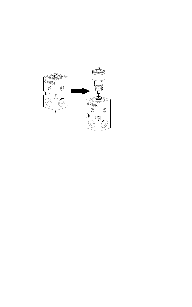
Module
Body
Piston/Cartridge
Assembly with
Needle Assembly
Figure 8: Removing Piston/Cartridge and Needle Assembly from Module Body
7. Remove large o-ring (9) from top of piston/cartridge assembly.
AG−900+ and AG900+S Applicators
23
2009 Nordson Corporation
Part 1098464A
AG900+/ Modules
a. See Figure 9. Loosen jam nut (3) on piston shaft and back nut up until against piston
shaft shoulder (4).
2
1
3
4
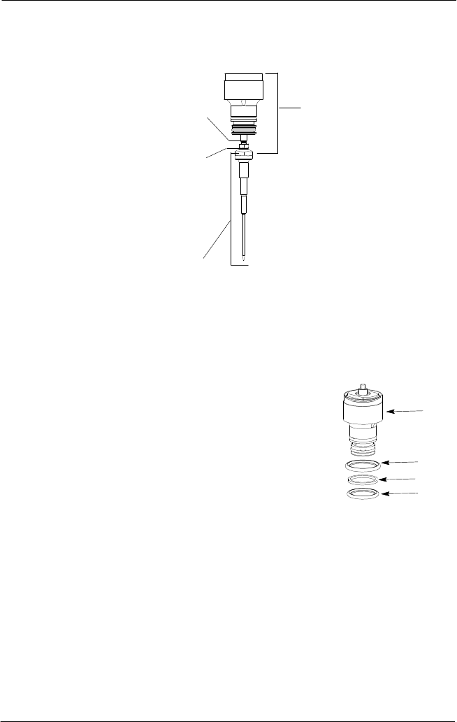
Figure 9: Piston/Cartridge Assembly and Needle Assembly
1. Piston/cartridge assembly
2. Needle assembly
3. Jam nut
4. Piston shaft shoulder
b. Unscrew old needle assembly from the piston/cartridge assembly.
NOTE: If piston assembly spins − put wrench on
wrench flats on top of piston.
c. See Figure 10. Remove o-rings and back-up ring from
piston/cartridge assembly.
Figure 10: Piston/Cartridge
Assembly and Needle
Assembly
1. Piston/Cartridge Assembly
2. Larger o-ring
3. Back-up ring
4. o-ring
1
2
4
3