AG900+ and AG900+S Applicators Customer Product Manual.pdf - 第34页
AG − 900+ and AG900+S Applicators 30 Part 1098464A 2009 Nordson Corporation Disassembly (contd) 2 3 9 4 6 8 5 1 1 7 10 Figure 17: AG-900+/AG900+S Applicator Assembly 1. Socket head screws 2. Air cap 3. Spring 4. Module…
AG−900+ and AG900+S Applicators
29
2009 Nordson Corporation
Part 1098464A
Replace the Piston/Cartridge Assembly
Disassembly
To disassemble your applicator to replace the piston/cartridge assembly, perform the
following procedure:
1. Heated applicators: disconnect and lock out input electrical power from the applicator.
NOTE: Do not remove the module from the regulator body or applicator adapter body
unless applicator location prohibits easy access.
NOTE: Standalone modules are mounted using threaded holes in the applicator body.
Remove screws before proceeding.
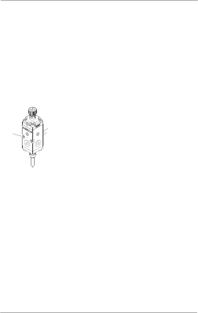
2. See Figure 16. If location requires the AG900+/AG900+S module to be removed from
the regulator or applicator body adapter to access components, do so by removing the
two socket head screws from the front of the module and pulling it free.
NOTE: Module must be pulled straight away
to avoid damage to locating dowel pins on
back face of module.
Figure 16: AG-900+/AG900+S Applicator Assembly
1. Socket head screw
2. Module body
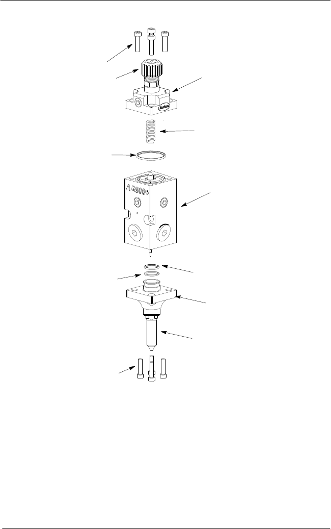
3. See Figure 17. Remove the four socket head screws (1), from the air cap (2) and then lift
the cap and spring (3) free of the applicator module.
2
1
AG−900+ and AG900+S Applicators
30
Part 1098464A
2009 Nordson Corporation
Disassembly (contd)
2
3
9
4
6
8
5
1
1
7
10
Figure 17: AG-900+/AG900+S Applicator Assembly
1. Socket head screws
2. Air cap
3. Spring
4. Module body with piston/cartridge and needle
assemblies installed
5. O-ring
6. Nozzle flange
7. Nozzle (reference only)
8. Back-up ring
9. Large o-ring (top of
piston/cartridge assembly)
10. Needle stroke adjustment knob
AG−900+ and AG900+S Applicators
31
2009 Nordson Corporation
Part 1098464A
4. Remove the nozzle (7)and nozzle flange (6) from the AG900+/AG900+S module by
removing the 4 socket head screws (1) from the nozzle flange (the nozzle will remain
attached to the flange). Do not remove nozzle from nozzle flange.
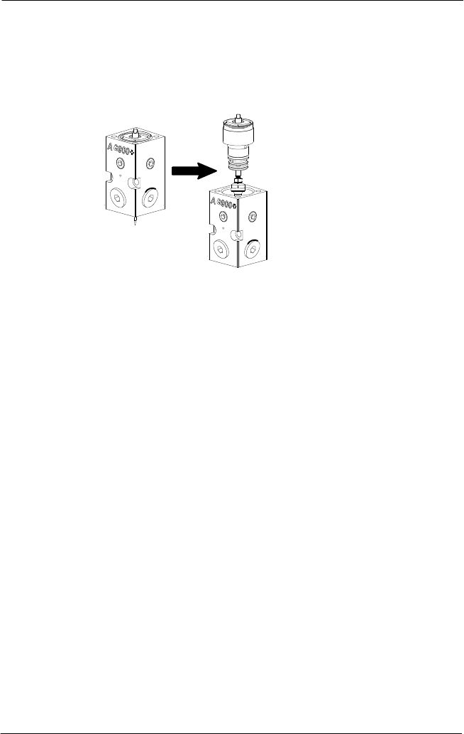
5. Push the piston/cartridge assembly and needle assembly (located inside of applicator
module body) out of the top of the module by pressing tip of needle assembly against a
soft surface (i.e. piece of wood or wood work surface).
Module
Body
Piston/Cartridge
Assembly with
Needle Assembly
Figure 18: Removing piston/cartridge and Needle Assembly from Applicator Module Body
6. Remove large o-ring (9) from top of piston/cartridge assembly.