AG900+ and AG900+S Applicators Customer Product Manual.pdf - 第20页
AG − 900+ and AG900+S Applicators 16 Part 1098464A 2009 Nordson Corporation Operation W ARNING! Allow only personnel with appropriate training and experience to operate or service the equipment. The use of untrained or…
AG−900+ and AG900+S Applicators
15
2009 Nordson Corporation
Part 1098464A
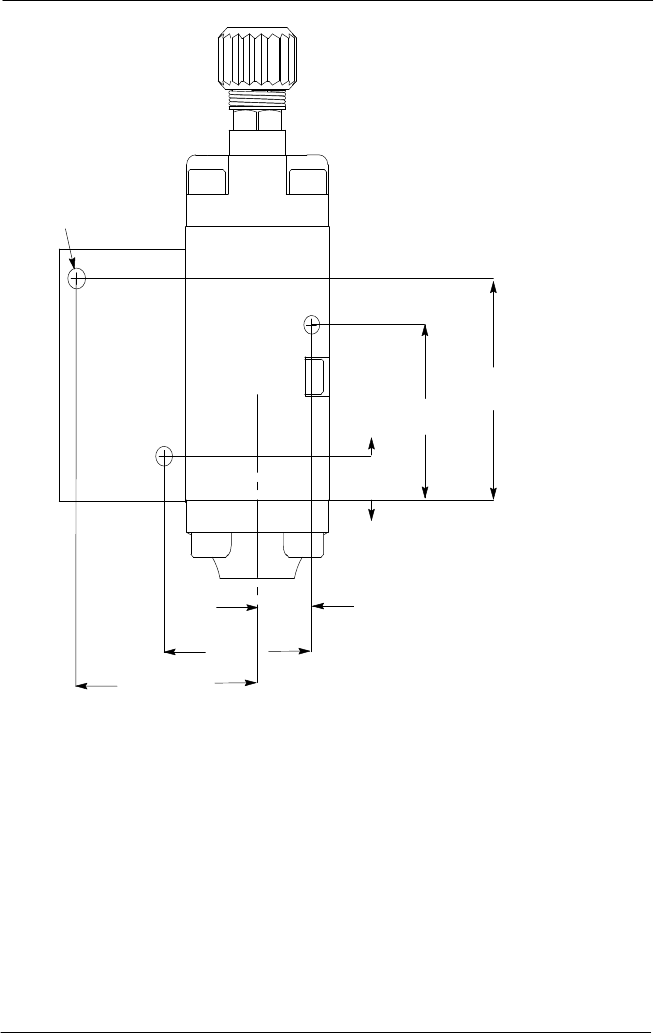
M5 Screw (X3)
48.25 mm
(1.90 in.)
42.67 mm
(1.68 in.)
9.65 mm
(.38 in.)
14 mm
(.55 in.)
39.88 mm
(1.57 in.)
54.36 mm
(2.14 in.)
Figure 4: Mounting Dimensions for AG-900+/AG900+S Applicator with Adapter Block
2. Position the applicator assembly against the customer-supplied bracket, and then
reinstall the three M5 screws and tighten securely.
3. Remove the steel hex cap from the
1
/
8
NPT port in the applicator body, and then thread
an air supply line to the port. Use PTFE tape or an equivalent on the air supply line.
4. See Figure 5. Thread a muffler to the air-close port.
NOTE: Order part number 1096469 solenoid assembly with tubing to use air-close.
5. Connect the air line(s) to an independently regulated, filtered, unlubricated and controlled
air supply.
6. For heated applicators only: connect the male plugs from the heater block adapter to the
female accessory connectors located on the heated hose or extension cords.
AG−900+ and AG900+S Applicators
16
Part 1098464A
2009 Nordson Corporation
Operation
WARNING! Allow only personnel with appropriate training and
experience to operate or service the equipment. The use of
untrained or inexperienced personnel to operate or service the
equipment can result in injury, including death, to themselves and
others, and damage to the equipment.
The needle and nozzle is typically installed onto the applicator at the factory.
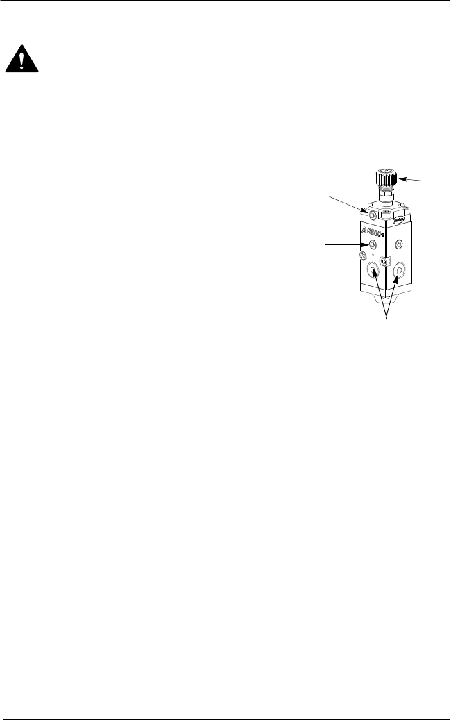
1. See Figure 6. Rotate the knurled needle adjustment knob
(1) clockwise until it stops.
2. Turn the adjustment knob 4−5 turns counterclockwise.
3. Apply material pressure to the applicator. Adjust the knob
until no material flows from the nozzle.
Figure 6: AG900+/AG900+S Module
1. Needle adjustment knob
2. Air close inlet
3. Air open inlet
4.
9
/
16
−18 in. SAE port
4. Apply air pressure to the applicator.
5. To adjust output pressure at the nozzle, turn the regulator adjustment screw clockwise to
increase pressure, counterclockwise to decrease pressure. Change setting on the melter
if no regulator is used.
NOTE: A change in pressure causes a change in maximum velocity and flow.
Pressure adjustments can be made with the applicator in the on or off position.
NOTE: Install a gauge into one of the
9
/
16
−18 inch SAE ports (4) monitor applicator
pressure.
NOTE: When using the air−close feature, adjust the air−close regulator for minimum
pressure by turning the air regulator adjustment screw counterclockwise several turns.
Make final adjustments to the air−close regulator to achieve good cut-off at the nozzle
after obtaining the material output flow rate.
The applicator is now ready for normal operation.
1
2
3
4
AG−900+ and AG900+S Applicators
17
2009 Nordson Corporation
Part 1098464A
Maintenance
WARNING! Allow only personnel with appropriate training and
experience to operate or service the equipment. The use of
untrained or inexperienced personnel to operate or service the
equipment can result in injury, including death, to themselves and
others, and damage to the equipment.
WARNING! Halogenated hydrocarbon solvents are dangerous when used to
clean components in a pressurized fluid system. The use of halogenated
hydrocarbons in the system could result in an explosion. Refer to Safety.
CAUTION! Never heat system components with a torch or an open flame. Use
an electric oven with forced air circulation or a flameless electric heat applicator.
Do not heat plastic parts above 230 C (450 F).
To keep the AG-900+/AG900+S applicator operating efficiently, follow a preventive
maintenance schedule. Refer to Table 3.
Maintenance Schedule
Table 2: AG-900+ Applicator Maintenance
Interval Activity
Daily Keep the unit free of dust.
Monthly Inspect all hydraulic, pneumatic, and electrical connections, nozzle,
and all other exterior parts. Repair, replace, and clean these parts
as necessary. Inspect hoses for kinks, fraying, and cuts. Replace
hoses, if necessary. Check for air leaks. If found, inspect all joints
and connections using a leak detector fluid. Refer to Parts for
ordering information. NOTE: Thoroughly wet any area using a leak
detector fluid and give sufficient time to detect bubbles.
Every 6 Months Rebuild or replace the regulator (if used).