AG900+ and AG900+S Applicators Customer Product Manual.pdf - 第24页
AG − 900+ and AG900+S Applicators 20 Part 1098464A 2009 Nordson Corporation Repair W ARNING! Allow only personnel with appropriate training and experience to operate or service the equipment. The use of untrained or in…

AG−900+ and AG900+S Applicators
19
2009 Nordson Corporation
Part 1098464A
Problem Possible Cause Corrective Action
3. Applicator or
swivel fails to
heat.
Loose connections Disconnect and lock out
power. Remove heater cover
and inspect wires. Restore
any loose connections.
Open or shorted heater Measure cold resistance
across the heater with a
VOM. 0 ohms means the
heater is shorted. Infinite
ohms means the heater is
open.
Open or shorted RTD Measure cold resistance
across the RTD with a VOM.
0 ohms means the RTD
shorted. Infinite ohms means
the RTD is open.
Short circuit in the cordset Measure cold resistance
between connector pins and
green ground lead in the
heater module. 0 or very low
resistance means the cordset
shorted. Replace cordset.
4. Bead is too large
or too small.
Dispense pressure set too
high or too low
Adjust material supply
pressure (if applicable).
Turn regulator adjustment
screw (if installed). If the
bead is still too large or too
small, replace the regulator
spring or adjust needle stroke.
5. Bead is
dispensed with a
hammerhead
(large to small).
Regulator operating outside of
normal pressure range
Turn regulator adjustment
screw counterclockwise. (If
applicable)
Worn regulator seat Rebuild regulator (If
applicable). Refer to the
Repair section.
AG−900+ and AG900+S Applicators
20
Part 1098464A
2009 Nordson Corporation
Repair
WARNING! Allow only personnel with appropriate training and
experience to operate or service the equipment. The use of
untrained or inexperienced personnel to operate or service the
equipment can result in injury, including death, to themselves and
others, and damage to the equipment.
WARNING! Disconnect equipment from line voltage. Failure to observe
thiswarning may result in personal injury, death, or equipment damage.
This section provides procedures for replacing AG-900+/AG900+S parts.
Replace the Needle/Nozzle
Disassembly
To disassemble your applicator to replace the nozzle/needle assemblies, perform the
following procedure:
1. Heated applicators: disconnect and lock out input electrical power from the applicator.
NOTE: Do not remove the module from the regulator body or applicator adapter body
unless applicator location prohibits easy access.
2. If location requires the AG900+/AG900+S module to be removed from the regulator or
adapter block to access components, do so by removing the two socket head screws
from the front of the module and pulling it free.
NOTE: Module must be pulled straight away to avoid damage to locating dowel pins
on back face of module.
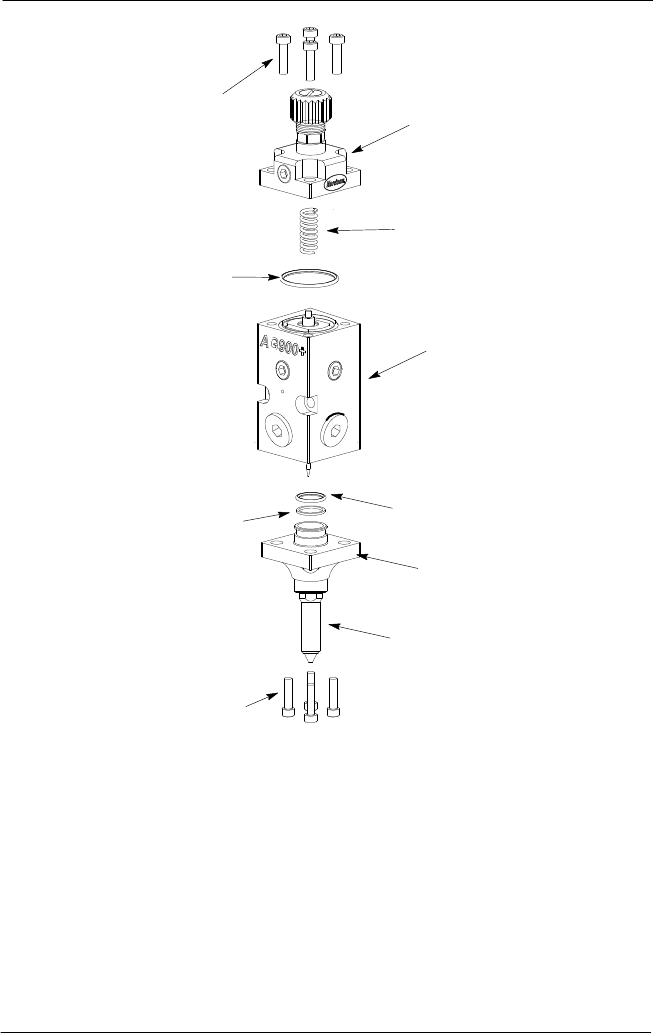
AG−900+ and AG900+S Applicators
21
2009 Nordson Corporation
Part 1098464A
2
3
9
4
6
8
5
1
1
7
Figure 7: AG-900+/AG900+S Applicator Assembly
1. Socket head screws
2. Air cap
3. Spring
4. Module body with piston/cartridge and needle
assemblies installed
5. O-ring
6. Nozzle flange
7. Nozzle
8. Back-up ring
9. Large o-ring (top of
piston/cartridge assembly)
3. See Figure 7.Remove the four socket head screws (1), from the air cap (2) and then lift
the cap and spring (3) free of the applicator module.