1034793-02_800_series_en.pdf - 第10页
10 Square wave signals Interface TTL RS 422 HTL HCHTL Supply 5 V dc 9-30 V dc 9-30 V dc 9-30 V dc Output signal 5 V dc 5 V dc 9-30 V dc 9-30 V dc Suitable for Low frequencies over short cables High frequencies over long …
9
MODULARITY
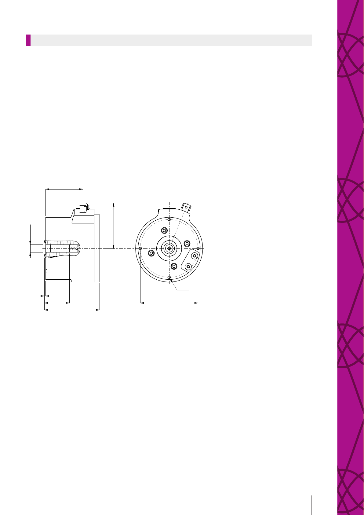
Model 841
Flameproof hollow shaft encoder intended for use in potentially explosive
atmospheres. Certied to be used on most markets.
Certication with
temperature class Tamb °C Rpm max
II 2G Ex db IIC T6
II 2D Ex tb IIIC T85°C -40°C…+40°C 4200
II 2G Ex db IIC T5
II 2D Ex tb IIIC T100°C -40°C…+60°C 4200
II 2G Ex db IIC T5
II 2D Ex tb IIIC T100°C -40°C…+70°C 1500
II 2G Ex db IIC T4
II 2D Ex tb IIIC T135°C -40°C…+70°C 6000
22.5
72
2
88
59.5
Ø92
40
4x M5
Ø12 G7
Ø107
4x M5
Ø100
10
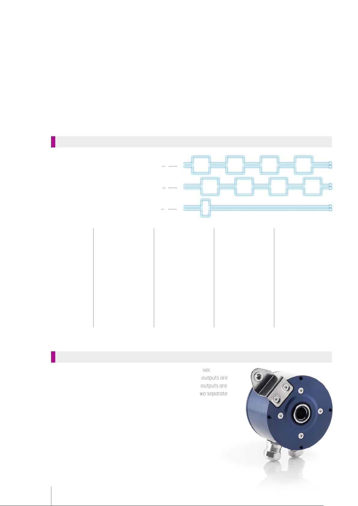
Square wave signals
Interface TTL RS 422 HTL HCHTL
Supply
5 Vdc 9-30 Vdc 9-30 Vdc 9-30 Vdc
Output signal
5 Vdc 5 Vdc 9-30 Vdc 9-30 Vdc
Suitable for
Low frequencies over
short cables
High frequencies over
long cables
High frequencies over
medium-length cables
Medium frequencies
over long cables
Max frequency
200 kHz 200 kHz 200 kHz 200 kHz
Max cable length
50 m at 50 kHz 1000 m (TiA/EIA -
422-B)
100 m at 100 kHz 350 m at 100 kHz
Dual outputs
Two separate encoders can be combined into one and the same cover.
This solution provides added safety in the form of redundancy, the outputs are
based on two separate scanning LED:s and electronic circuits. The outputs are
galvanically insulated from each other and may be connected to two separate
systems for dierent functions or for redundancy.
Available in model 855 and 865
Electronics
2 (S00)
2 (S00)
1 (S90)
1 (S90)
0 (S ref)
0 (S ref)

11
MODULARITY
Sine wave signals
Sine waves are an alternative form of output signal. The analogue signal produces a
unique amplitude for each position on the wave, allowing interpolation and very high
resolutions. The interface 1 Vpp is often used in safety-critical applications where
detection is required of extremely small movements.
Available in model 801, 803, 850, 861 and 862
Digital speed over PROFIBUS
With this option the encoder has two dierent connections, one with a standard
incremental output and another for communication over PROFIBUS.
The standard incremental pulse output is used for connection to the inverter for
direct speed control, while the additional PROFIBUS output can be connected to
another system where a reference value of the speed is required. The speed is calcu-
lated internally in the encoder and is sent over the eldbus.
Available in model 850, 861 and 862
Optolink transmission integrated
System for transmission of incremental encoder signals in an optical bre can be
integrated into the encoder. This is suitable for use in environments with high elec-
tromagnetic disturbances, transmission of signals over long distances (up to 1,5 km)
and where galvanic insulation is required.
Available in model 801, 803 and as a separate Optolink module
(CRG Optolink)