OM-1683-001_w.pdf - 第17页
OM-1683 Cont-4 Contents Page 1 103-001 15. Pneumatic and Electrical Diagrams ............................................... 39 15.1 Pneumatic and Mounting Diagrams ........................................ 39 Conveyor (P…

OM-1683
Cont-3
Contents
Page
1103-001
13. Maintenance ...................................................................................
26
13.1 Outline of Maintenance ........................................................... 26
13.1.1 Notes on Maintenance ................................................... 26
13.1.2 Preparation for Maintenance ......................................... 27
13.1.2.1 Preparation for Cleaning ........................................ 27
13.1.2.2 Preparation for Lubrication ..................................... 28
13.1.3 Items for Periodic Maintenance ..................................... 31
13.2 Maintenance Check List ......................................................... 32
13.2.1 Weekly Maintenance ..................................................... 32
13.2.2 Quarterly Maintenance .................................................. 32
13.2.3 Half-Yearly Maintenance ............................................... 32
13.3 Maintenance Spots ................................................................. 33
13.3.1 Whole View .................................................................... 33
13.3.2 Inspection, Cleaning, and Lubrication stops .................. 34
13.3.2.1 PCB Positioning Section ........................................ 34
13.3.2.2 Conveyor Section ................................................... 35
14. List of Important Servicing Parts .................................................... 38

OM-1683
Cont-4
Contents
Page
1103-001
15. Pneumatic and Electrical Diagrams ...............................................
39
15.1 Pneumatic and Mounting Diagrams ........................................ 39
Conveyor (Pneumatic Diagram) .................................... 39
Conveyor (Mounting Diagram) ...................................... 40
15.2 Sensor and Load Layout ......................................................... 41
Conveyor Section Layout (Outside : A-Lane) ................ 41
Conveyor Section Layout (Outside : B-Lane) ................ 42
Conveyor Section Layout (Inside : A-Lane) ................... 43
Conveyor Section Layout (Inside : B-Lane) ................... 44
15.3 Parts Location ......................................................................... 45
Conveyor Section Layout .............................................. 45
15.4 Circuit Diagram ....................................................................... 46
Conveyor M Circuit Diagram (1) .................................... 46
Conveyor M Circuit Diagram (2) .................................... 47
Conveyor M Circuit Diagram (3) .................................... 48
Conveyor M Circuit Diagram (4) .................................... 49
Conveyor M Circuit Diagram (5) .................................... 50
Conveyor M Circuit Diagram (6) .................................... 51
Conveyor M Circuit Diagram (7) .................................... 52
Conveyor M Circuit Diagram (8) .................................... 53
Conveyor M Circuit Diagram (9) .................................... 54
Conveyor M Circuit Diagram (10) .................................. 55
U08 I/O P.C.B. STLT CNVR (L) ..................................... 56
U08 I/O P.C.B. STLT CNVR (R) ..................................... 57
15.5 Cable Connection Diagram ..................................................... 58
Dual Transfer Harness Connection Diagram 1 .............. 58
Dual Transfer Harness Connection Diagram 2 .............. 59
16. Specications ................................................................................. 60
1
OM-1683
1. Scope
In the dual transfer mode (PCB transfer using two transfer lanes), the PCBs
with the size (Direction Y) up to 250 mm, can be produced simultaneously.
The transfer specications do not comply with the SMEMA transfer
standards.
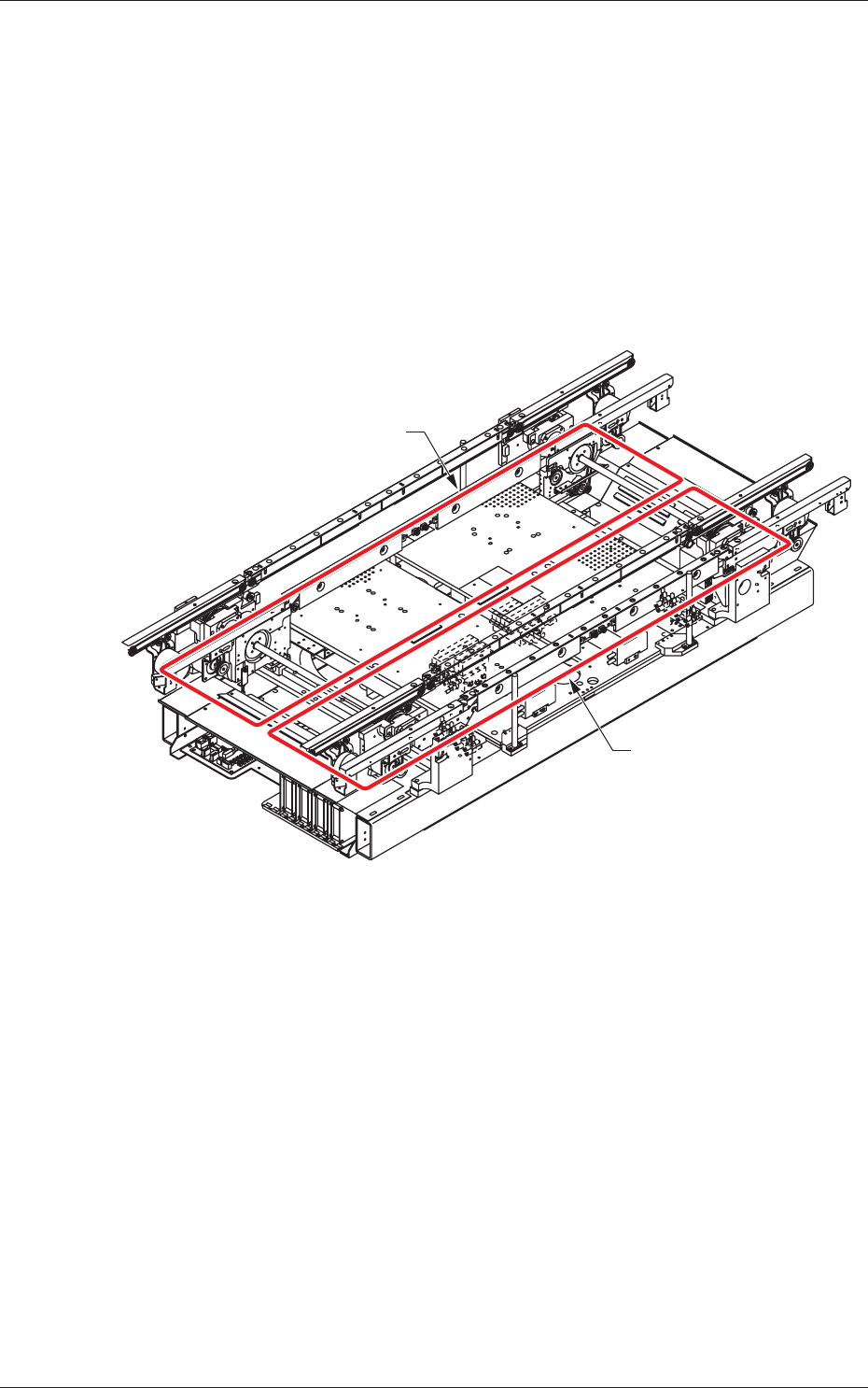
2. Rough View of Machine
Front Side of Machine
Lane A
Lane B
Fig. 1
1103-001
1. Scope