OM-1683-001_w.pdf - 第81页
64 OM-1683 Item Description 7. Operation Scope The machine starts component placement on either one (positioned one) of the PCBs on the two transfer lanes. After the machine has completed component placement on the PCB o…
63
OM-1683
1103-001
16.Specications
Item Description
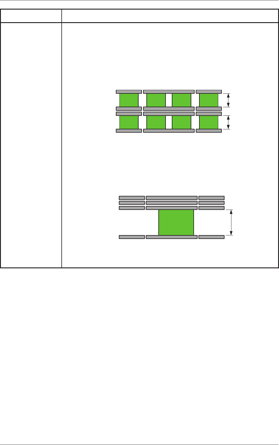
6. Transfer Mode There are two modes; One is the dual transfer mode that uses two transfer lanes and the
other is the single transfer mode that uses one transfer lane.
However, in the case of the dual transfer mode, the PCB width should be up to 250
mm.
•
Dual Transfer Mode (Dual Transfer for Two PCBs at the same time)
In the case of a PCB width between 84 mm and 250 mm, the dual transfer
operation is available using both lanes.
Max. 250 mm
Max. 250 mm
Chute
A (Fixed)
Chute
A' (Movable)
Chute
B (Movable)
Chute
B' (Fixed)
Buffer Section Buffer Section
Front Side of Machine
Positioning Section
• Single Transfer Mode (Dual Transfer for Single PCB)
In the case of the PCB width between 84 mm and 415 mm, the single transfer is
available by means of moving the two inside rails (Chute A', Chute B) together to
the rear side.
Max. 415 mm
Chute A (Fixed)
Chute A' (Movable)
Chute B (Movable)
Chute B' (Fixed)
Buffer Section Buffer Section
Front Side of Machine
Positioning Section
64
OM-1683
Item Description
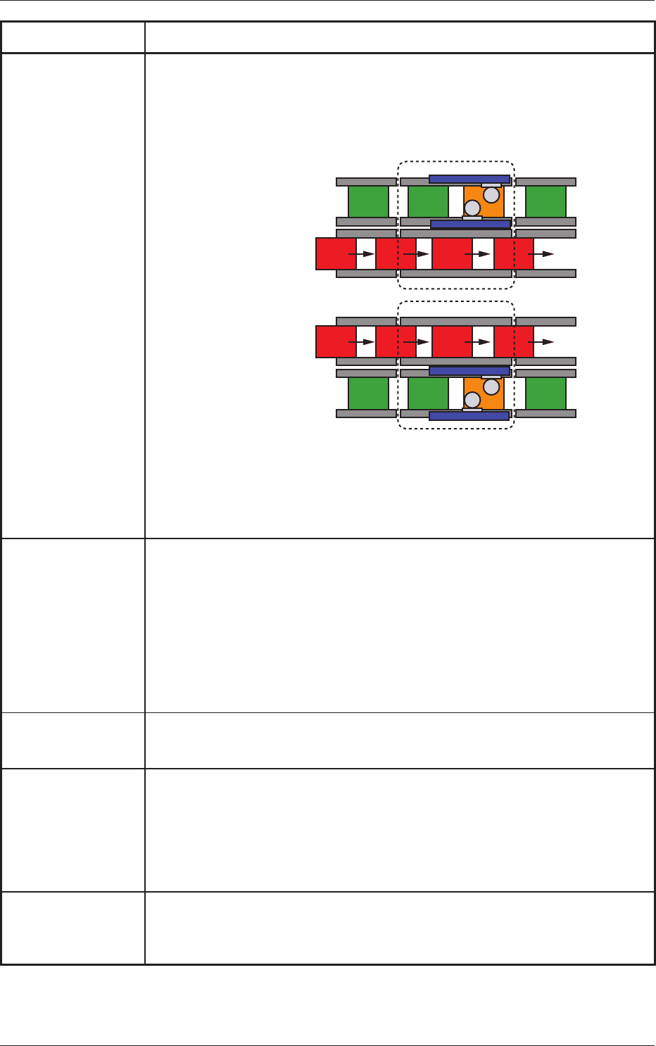
7. Operation Scope The machine starts component placement on either one (positioned one) of the PCBs
on the two transfer lanes.
After the machine has completed component placement on the PCB on one lane, it
starts placement on the PCB on the other lane.
Lane A : Placement
Lane B : Transfer
Lane A : Transfer
Lane B : Placement
Process
Position
Process
Position
The two PCBs are transferred one by one alternatively and the component placement
is performed on a single PCB in either of the Lane A and Lane B, which enables
successive component placement without considering the PCB transfer time.
(Nominal PCB transfer time is zero).
8. PCB Replacement
Time
Dual Transfer Mode :
0 second (Note)
Single Transfer Mode : Within 2 seconds
(260 mm or less in PCB length)
Notes :
(a) When the PCBs are transferred one by one alternatively on the two lanes,
the nominal PCB transfer time becomes zero.
However, the condition is that "Height of the both the previously-placed
component and placed component should be 12.
7 mm or less".
(b) When the production on one lane only is continued, the PCB replacement
time is the same as for the single transfer mode.
9. T
ransfer Height 905 mm (Transfer Reference Height)
Note :
For the SMEMA Height, a separate option is required.
10. Automatic Setup
function
• Automatic
Width Setup function
Standard Design with Two Modes; Dual Transfer Mode and Single Transfer Mode
• Backup Up/Down Function
Standard Design with Divided Type for Dual Transfer
• Support Pin Change
Standard Design with the Support Pin Automatic Setup Function
11. Pattern Program The two PCBs are transferred one by one alternatively for each PCB transfer lane.
Therefore, the pattern programs shall be prepared individually for each PCB transfer
lane.
16.Specications
1103-001

65
OM-1683
1103-001
16.Specications
Item Description
12. Hardware
Signal Connection for Input and Output Machines
Two types of I/F systems are provided independently for both input and output
machines.
Signal paths (paths for signals from/to the input & output machines and the furnace)
can be connected to the I/F board of the input and output machines.
Signal Connections in Dual and Single Transfer Modes
Dual
Transfer Mode : 2 systems
Single Transfer Mode : 1 system
13. Input and Output
Interfaces
Conforming to the specications of the SMEMA communications.
1
4. Dimensions Approx. 1,280 (W
idth) mm (Including Input / Output Conveyor)
× 2,232 (Depth) mm (Including Bank Feeder Change Cart)
× 1,
450 (Height) mm (1,910 mm : Including Light Tower)
15. Mass Approx. 1,800 kg (Excluding Bank Feeder Change Carts and Feeders.)