OM-1683-001_w.pdf - 第33页
16 OM-1683 8. "PCB.CNT ." Window This window enables the operator to set the PCB production count for each lane. Reference Refer to "8. "PCB.CNT ." W indow" in Chapter 6, V olume 2, in the S…

15
OM-1683
(7) Open the transparent cover.
CAUTION
The load power to the motors, etc., is turned OFF
but the setup operation must be performed carefully
when you put your hand inside the machine. Avoid
handandngerinjuries.
(8) Slightly push the PCB by nger to conrm that there is no problem in the
location of the support pins.
(
9) Close the transparent cover.
(10) Press the cover lock switch to turn on the lamp.
1103-001
7.1ConrmationofPCBTransferandPositioning
16
OM-1683
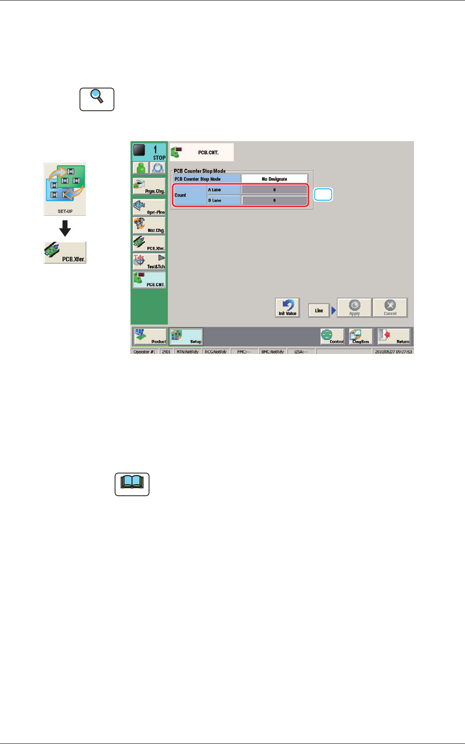
8. "PCB.CNT." Window
This window enables the operator to set the PCB production count for each
lane.
Reference
Refer to "8. "PCB.CNT." Window" in Chapter 6, Volume 2, in the
SIGMA-G5 main machine instruction manual for the information other
than for dual transfer.
[1]
Fig. 16 PCB. CNT.
[1] Count
A Lane, B Lane
The number of produced PCBs for each lane for stopping the machine using
the PCB Counter Stop Mode, is set in this group box.
Note
The set count is displayed in the "Count" data box in the "AUTO. OPN"
window.
Graphic
Development
1103-001
8. "PCB.CNT." Window
17
OM-1683
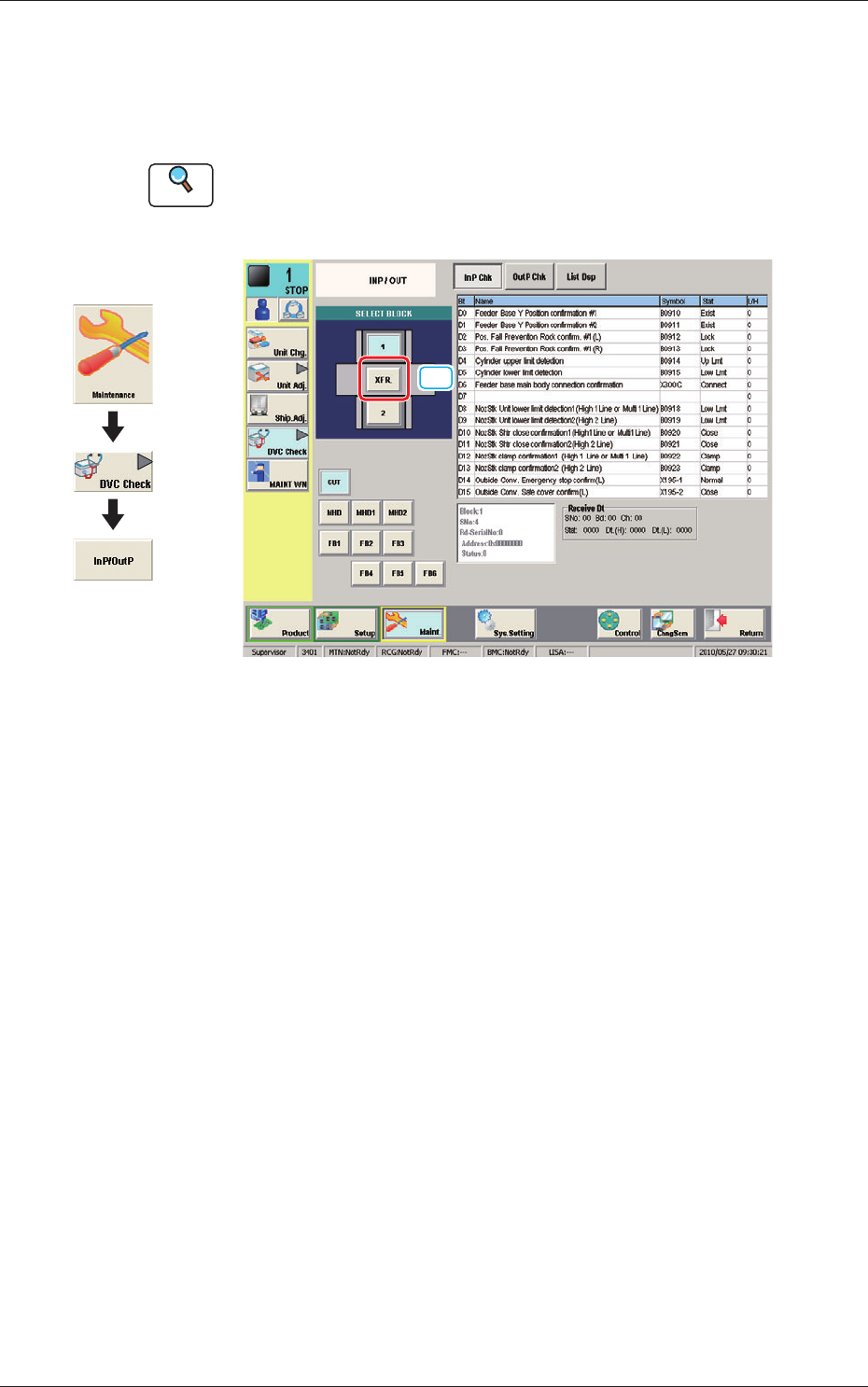
9. "INP/OUT" Window
This window enables the operator to conrm the input/output status for the
PCB transfer.
Reference
Refer to "6.1 "INP/OUT" Window" in Chapter 1, Volume 3, in the
SIGMA-G5 main machine instruction manual for the information other
than for dual transfer.
[1]
Fig. 17 INP/OUT
[1] [XFR.] Button
When pressed the conrmation of the input/output status for the PCB transfer
is available.
Graphic
Development
1103-001
9. "INP/OUT" Window