00198611-01_IM_712.0_R18-2_EN.pdf - 第62页
Station Software Ver sion 712.0 (R18 - 2) / Installation Manual 11/2018 Edition 62 7 First Booting after Installa tion When a machine is boote d for the first time af ter installation, the s tation software det ects for …
Station Software Version 712.0 (R18-2) / Installation Manual 11/2018 Edition
61
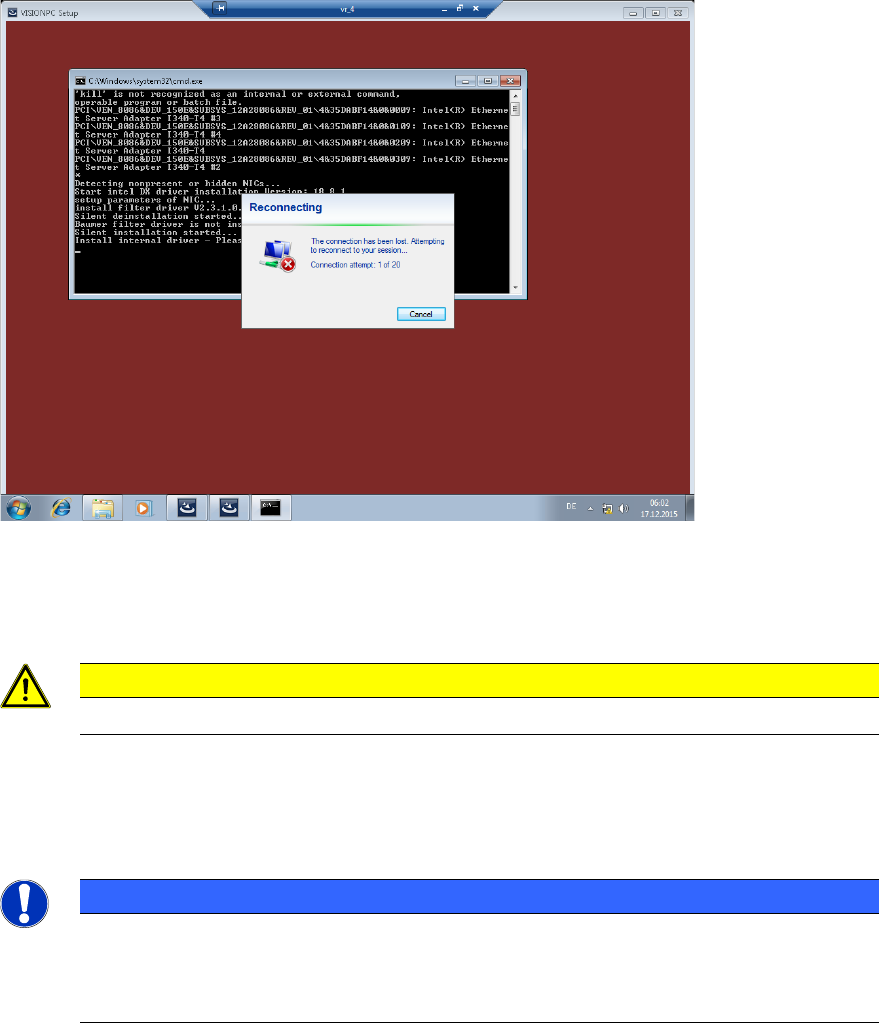
Due to the network card settings, the remote connection might hang up during the installation. If
nothing has changed on the screen after a minute:
► Move the mouse until the following message is displayed.
Figure 6-13: Reconnecting remote connection
After a short waiting time, the connection will be automatically re-established.
The necessary files for the respective software will be installed on the Vision computer.
CAUTION
The Vision computer must not be simply switched off!
► Open the Command Prompt window under Start – All programs – Accessories.
► Run the shutdown/s command.
The shutdown starts and the Remote Desktop is terminated.
NOTICE
To establish the connection between the SIPLACE Coplan computer software or feeder
computer software and the SIPLACE station software after the installation has been
completed, the Vision computer and the station computer must first be shut down and
the machine then switched off completely.
► To do this, open the Start menu on the station computer and select All Programs – ASM
Station-SW-7xx – Shutdown all computer.
► Switch the machine off when the computer systems have shut down.
► Then, switch the machine on again. This reboots the Vision computer and the station computer.
Station Software Version 712.0 (R18-2) / Installation Manual 11/2018 Edition
62
7 First Booting after Installation
When a machine is booted for the first time after installation, the station software detects for the
most part independently which hardware components are used via the Auto-Configuration
feature. Certain settings, such as CAN card type, table type, lamp indicators and pin magazines
cannot be detected automatically and must be selected manually.
Generally, the operator will be prompted to confirm or reject any configuration changes.
By clicking the + sign in front of the auto-configuration text, the message list opens and the used
hardware components are displayed.
The Machine service activity level is required to execute the auto-configuration. The activity level
can be changed under Settings – User.
Required manual entries
The entries to be selected manually in the Value column are tagged with a '?' (question mark). All
these values must be adapted before the auto-configuration can be finished.
As of station software version 705.03 you must set, whether the lamp indicators on the placement
machine towers shall be displayed two-colored (green / white) or three-colored (green / white / red)
for all placement machines of the SX-series and DX-series. More information about the two lamp
indicator systems can be found in the Feature Description of the station software, item number
[00197741-xx].
7.1 X-Series Placement Machines
► If the Coplan computer has been installed, you must additionally confirm or reject the 3D
Coplan sensor in the auto-configuration.
7.2 X-Series S Placement Machines
► When the X-Series S placement machines are booted for the first time you must select the
CAN card (two or four CAN buses):
7.2.1 X4i S Placement Machine
► When the X4i S placement machine is booted for the first time you must select the following
options manually:
– If a TrayStak Feeder is used, this must be defined for each location concerned in the auto-
configuration.
– Table position (inner and outer)

Station Software Version 712.0 (R18-2) / Installation Manual 11/2018 Edition
63
7.3 SX-Series Placement Machines
The System identification calibration feature has been introduced for the SX-series placement
machines in the automatic calibration. Therefore, an additional calibration step may be required
after installation. In this case, a warning is displayed that the calibration is not up to date. This also
applies for the respective station software version in compatible mode. Proceed as follows:
► Log in on the Machine service activity level.
► Switch to the Configure, update and calibrate machine menu.
► Press the Automatic calibration button.
The following dialog box is displayed:
Figure 7-1: Calibration steps dialog box
► Select the System identification calibration step.
Or
► Select Selection – Gantry axes calibration.
All required calibrations will then be performed for the main axes and the machine provided
with the current data.