CP-7[732-742]-series Mechanical Reference(2.9E).pdf - 第123页
3.3 Replacing the W aste T ape Cutter Point A broken or damaged waste tape cutter will be unable to cut the waste tape properly, causing tape clogging and tape feed problems. The waste tape cutter must be replaced at suc…
7. Use a cutter to trim off any of the sticker which protrudes beyond the disk.
8. Remove any of the adhesive which may have adhered to the nozzle tube.
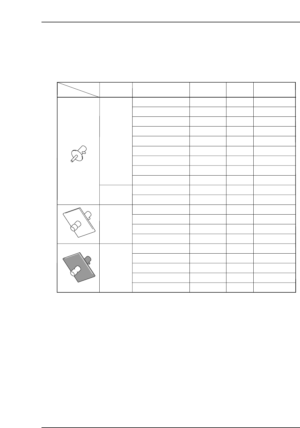
Nozzle and fluorescent sticker drawing numbers
ADCPH751✽
ADCPH769✽
ADCPH752✽
ADCPH753✽
ADCPH754✽
ADCPH955✽
ADCPH956✽
ADCPH957✽
ADCPH958✽
ADCPH770✽
ADCPH971✽
ADCPH959✽
ADCPH961✽
ADCPH963✽
ADCPH965✽
ADCPH960✽
ADCPH962✽
ADCPH964✽
ADCPH966✽
ADCPH968✽
θ8
θ8
θ8
θ8
θ8
θ16
θ16
θ16
θ16
θ8
θ16
16x16
16x16
16x16
16x16
16x16
16x16
16x16
16x16
21x21
DCPH851✽
DCPH851✽
DCPH852✽
DCPH853✽
DCPH854✽
DCPH855✽
WPH820✽
WPH821✽
DCPH856✽
DCPH854✽
WPH820✽
DCPH857✽
DCPH858✽
DCPH859✽
DCPH860✽
DCPH881✽
DCPH882✽
DCPH883✽
DCPH884✽
DCPH885✽
T050a
Nozzle SizeNozzle shape
Round
Round
Round
Melf
Nozzle Assy
Dwg. No.
Disk Size
Fluorescent Seal
Dwg. No.
θ0.4 ( R08-004 )
θ0.4 ( R08-004 )
Short
θ0.7 ( R08-007 )
θ1.0 ( R08-010 )
θ1.3 ( R08-013 )
θ1.8 ( R16-018 )
θ2.5 ( R16-025 )
θ3.7 ( R16-037 )
θ5.0 ( R16-050 )
θ1.3 ( M08-013 )
θ2.5 ( M16-025 )
θ1.8 ( S16-018 )
θ2.5 ( S16-025 )
θ3.7 ( S16-037 )
θ5.0 ( S16-050 )
θ1.8 ( B16-018 )
θ2.5 ( B16-025 )
θ3.7 ( B16-037 )
θ5.0 ( B16-050 )
θ5.0 ( B21-050 )
Part 3 Chapter 3 Replacing Consumable Parts
Edition 2.7 3-3-3 CP-7 series Mechanical Reference
3.3 Replacing the Waste Tape Cutter
Point
A broken or damaged waste tape cutter will be unable to cut the waste tape properly,
causing tape clogging and tape feed problems. The waste tape cutter must be replaced at
such times.
Procedure
WARNING
• Turn the main power off before performing this
procedure.
• Rotation may occur (caused by spring action) if the cam
axis is not at its origin position (0-degrees).
Use special care when working inside the machine as
this is a dangerous area.
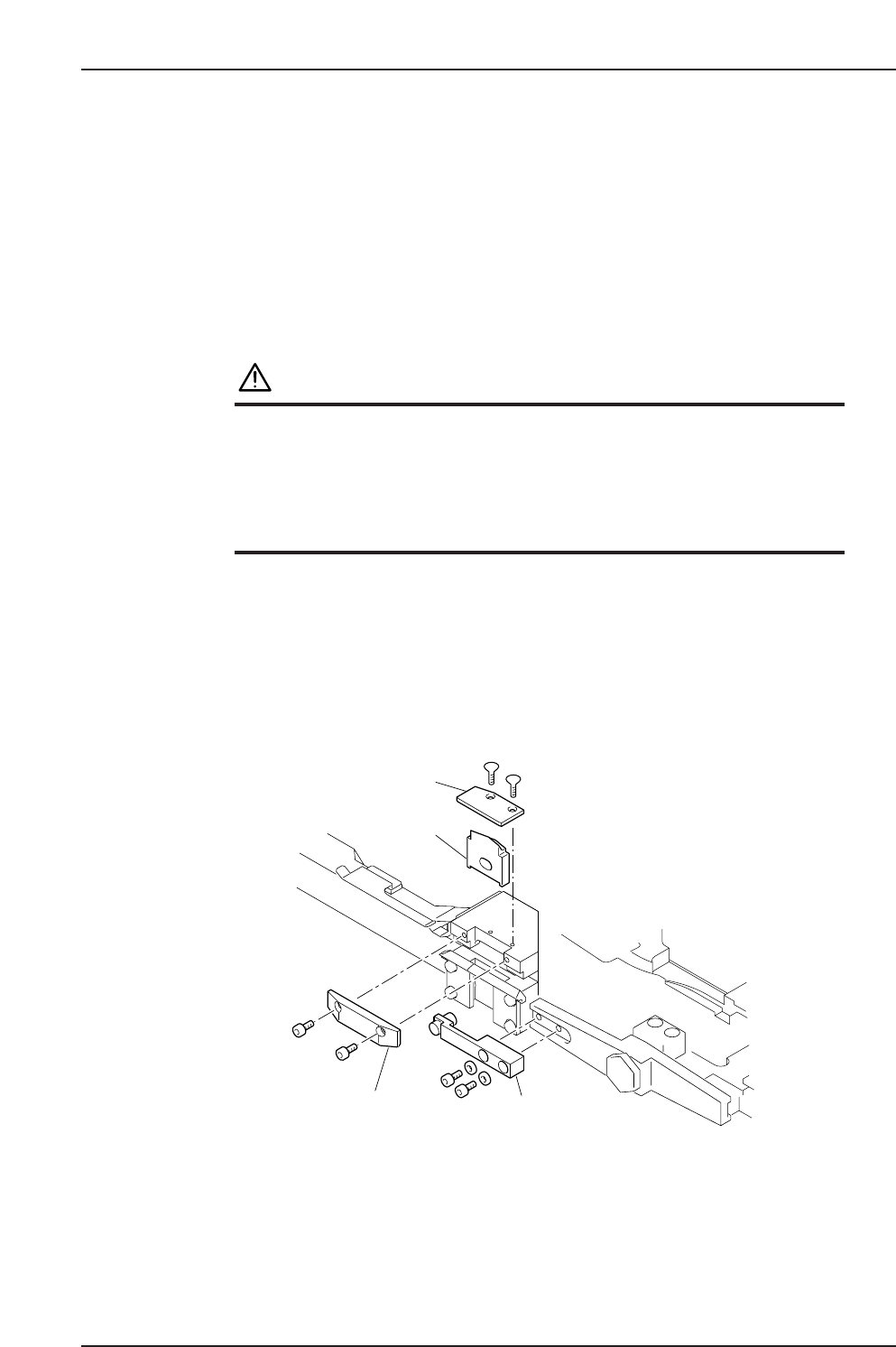
1. Remove the plate located above the waste tape cutter.
2. Remove the two bolts which secure the fixed cutter.
3. Remove the two bolts which secure the arm of the moving cutter.
4. Remove the fixed and moving cutters, and mount the new fixed and moving
cutters.
Note: Apply grease to the contact points before attaching the moving cutter.
(See 2.6 Lubricating the Tape Cutter)
C7SM3052a
Moving cutter
Fixed cutter
Arm
Plate
Part 3 Chapter 3 Replacing Consumable Parts
Edition 2.7 3-3-4 CP-7 series Mechanical Reference
3.4 Replacing Conveyor Belts
Point
Broken or damaged conveyor belts must be replaced.
Procedure
WARNING
Be sure to turn the main power off before performing this
procedure.
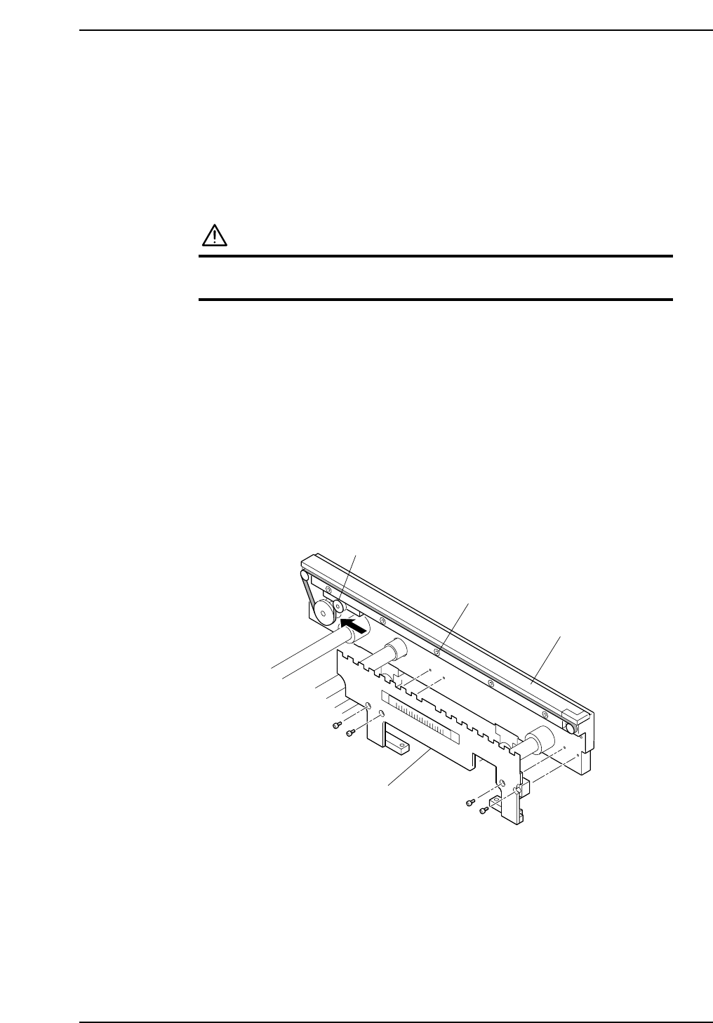
1. Remove the panel lifter.
2. Loosen the bolt which secures the tension pulley and weaken the tension.
3. Loosen the belt guide bolts.
4. Replace the conveyor belt.
5. Insert a 0.3 mm clearance gauge between the belt’s top surface and the plate, then
tighten the belt guide bolts while maintaining this 0.3 mm clearance.
6. Tighten the belt by applying 1 to 1.5 kg of force to the tension pulley in the
direction indicated by the arrow, then tighten the tension pulley bolt.
Note: The belt can also be tightened to the prescribed tension by tightening the tension
pulley bolt while pushing the tension pulley 1 to 2 mm in the direction indicated by
the arrow.
C7SM3053a
Belt guide bolt
Panel lifter
Tension pulley
Plate
Part 3 Chapter 3 Replacing Consumable Parts
Edition 2.7 3-3-5 CP-7 series Mechanical Reference