CP-7[732-742]-series Mechanical Reference(2.9E).pdf - 第213页
1.5 Missing Parts No. M: Part 3 Chapt 1 M: Part 3 Chapt 3 "3.1" M: Part 2 Chapt 2 M: Part 4 Chapt 1 "1.1 1" 5-1 5-2 5-3 5-4 5-5 5-6 T : Part 3, Lesson 2 "2.1.3" U: Part 2 Chapt 4 "Nozzl…

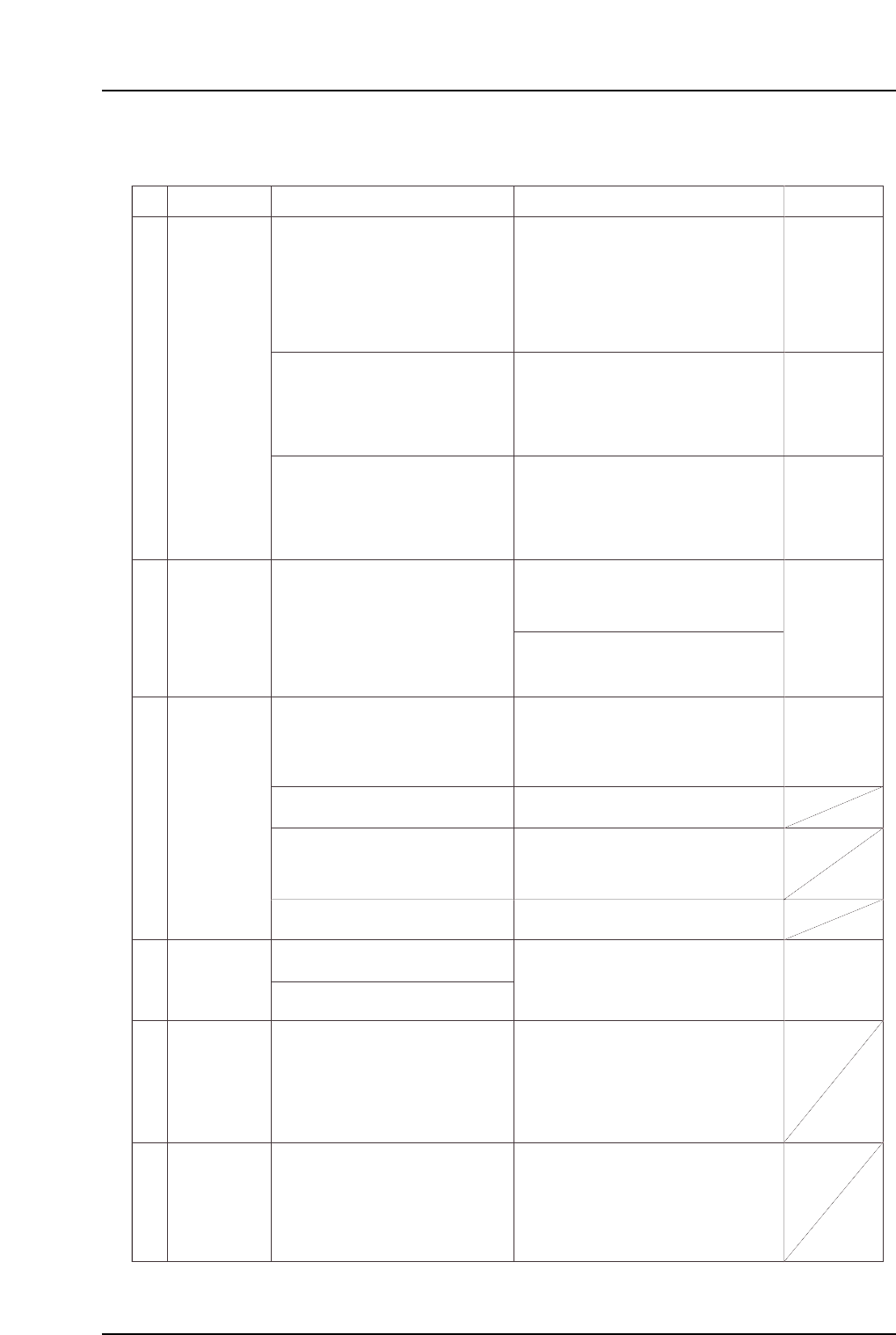
Part 5 Chapter 1 Troubleshooting Table
Edition 2.7 5-1-9 CP-7 series Mechanical Reference
No.
4-16
4-17
M: Part 1
Chapt 3
M: Part 1
Chapt 3
S: Part 3
Chapt 1
XY-table clamp
error
(1) Verify that the XY-table is clamping panels
properly.
(2) Check the following sensors for problems
(3) - (6) (see above).
• Panel was clamped, but the clamp
sensor failed to switch on, and the
unclamp sensor failed to switch off.
• Panel was unclamped, but the
unclamp sensor failed to switch on,
and the clamp sensor failed to switch
off.
The clamping cylinder may not be
moving all the way to its motion limit
position.
Reference pin insertion sensor fails to
switch on.
XY-table reference pin insertion check X059
XY-table raised clamper check X05A
XY-table panel clamp check (fixed-rail side, right) X05F
XY-table panel clamp check (adjustable-rail, right) X060
XY-table panel unclamp check (fixed-rail, righ X061
XY-table panel unclamp check (adjustable-rail, right) X062
XY-table panel clamp check (fixed-rail, left) X063
XY-table panel unclamp check (fixed-rail, left) X064
(1) Check the following sensors for problems
(3) - (6) (see above).
XY-table
unclamp error
Cause Remedy Remarks Ref. Page
(3) Check the panel clamping/unclamping
cylinder for problem (7) (see above).
Execute the following commands to see if the
cylinder can be moved to its motion limit position:
[Panel Loader]-[Clamp/Unclamp]-[START].
* The "X???" and "Y???" values which appear in the remedy column correspond to
the I/O map assignment numbers.
1.5 Missing Parts
No.
M: Part 3
Chapt 1
M: Part 3
Chapt 3 "3.1"
M: Part 2
Chapt 2
M: Part 4
Chapt 1 "1.11"
5-1
5-2
5-3
5-4
5-5
5-6
T: Part 3,
Lesson 2
"2.1.3"
U: Part 2
Chapt 4
"Nozzle"
"Speed"
T: Part 3
Lesson 2
"2.1.3"
U: Part 2
Chapt 4
"Speed"
T: Part 3
Lesson 2
"2.1.1"
U: Part 2
Chapt 4
"Appearance"
Incorrect Part
data setting.
Specify the appropriate nozzle size and
cam speed settings using the Tech
Report issued by Fuji as a reference.
If accuracy deviations or missing parts
are occurring for a specific part,
decrease the XY table speed setting in
the Part data where the problem is
occurring.
Unsuitable nozzle size, part weight, and cam
speed, etc., settings can result in an
insufficient holding force when handling
parts, causing nozzle and part slippage.
The Fuji Tech Report is meant for reference
purposes only.
The recommended cam speed may be
different even if the part shape is the same.
An unsuitable XY table speed can apply a
force which exceeds the holding capacity of
the part's solder, resulting in position
deviations. Solder adhesion decreases
when it dries. Therefore, the sooner
placement occurs after printing, the better.
Errors in the part height information or in the
table reference height Proper data
information can cause missing parts.
Fuji recommends that the actual part be
measured, with the measured value being
entered as the part height setting in Part data.
A stuck nozzle will prevent the parts from
being pushed in far enough when being
mounted, and may result in the parts being
returned.
Parts may be returned if solder, etc., is
adhering to the nozzle tip.
A misalignment between the ST9 nozzle
DOWN limit and the board height can
prevent parts from being pushed in far
enough when being placed, and may affect
placing accuracy.
Note: If a problem is found, contact your Fuji
agent.
Note: Machine adjustments can be performed
only by those with a Level 3 training.
Vacuum break problems can result in parts
being returned.
The solder printing condition or dryness can
cause part deviations during board
conveyance, or can affect the self-alignment
at reflow operations.
Solder adhesion weakens when the solder
dries. Therefore, the sooner placement
occurs after printing, the better.
Improper reflow conditions can cause self-
alignments and tombstoning.
Provide a profile in which the temperature is
increased evenly over the entire board. If the
solder's melting speed differs from point to
point, parts will be pulled toward the solder
that melts first.
Improper ST9 cylinder operation may
prevent parts from being placed correctly.
Note: If a problem is found, contact your Fuji
agent.
(1) Press the reflective disk to verify
that the nozzle spring-back motion
is smooth.
(2) Check to see if the nozzle is clogged.
(3) Check to see if foreign matter has
adhered to the nozzle tip.
Replace the nozzle if any of the above
problems are found.
Defective
nozzle.
Placement
height problem.
Vacuum break
problem
Printing
conditions
problem.
Reflow
conditions
problems.
Cause Remedy Remarks Ref. Page
Check for errors in the part height
information.
Check the backup pin height, quantity,
and configuration, and check the board's
flatness.
Check to see if the XY-table is level.
Replace the cylinder unit if abnormal
noise is emitted from the cam box
uring automatic operation, or if the
nozzle DOWN limit position is incorrect.
Check for a problem with the Proper
data Z0 (0.3mm push in).
Replace mechanical valves where the
spool motion is not smooth.
Adjust the vacuum break lever position
and the speed controller.
Check the solder condition after printing.
Check the reflow temperature profile.
Part 5 Chapter 1 Troubleshooting Table
Edition 2.7 5-1-10 CP-7 series Mechanical Reference
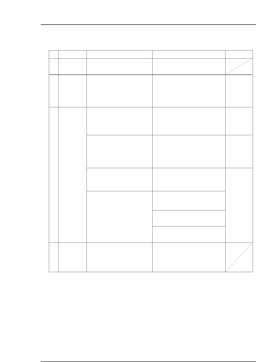
1.6 Part Height Sensor Errors
No.
6-1
6-2
6-3
6-4
M: Part 3
Chapt 1 "1.8"
M: Part 3
Chapt 1 "1.4"
M: Part 3
Chapt 3 "3.1"
T: Part 3
Lesson 2
"2.1.1"
U: Part 2
Chapt 4
"Appearance"
T: Part 3
Lesson 2
"2.1.1"
Nozzle length
warning
displays
Replace the nozzle where this warning
occurs, then easure the nozzle length
again.
If the measured nozzle length exceeds the
permissible value, a warning displays
onscreen.
This error occurs when dust has adhered to
the part height sensor's camera lens.
Automatic operation continues unless the
quantity of dust is such that it hinders the
measurements.
Note: Clean away the dust using cotton
swab, etc.
Error occurs because the Part data setting
differs from the height of the part which was
picked up.
Error occurs because an unsuitable part
height tolerance value is specified in Part
data. The tolerance value varies according
to the part type. Verify that the tolerance
value is appropriate for the part in question.
(Refer to the tolerance values recommended
by Fuji.)
A part may be picked up in a tombstoned
posture if the nozzle length measurement
result differs from the actual nozzle length
When using part height information, measure
the nozzle length before production begins.
A bent nozzle will cause a deviation in the
part pickup position, and may result in the
part being picked up in a tombstoned
posture.
A stuck nozzle cannot adequately reach the
part, and may result in the part being picked
up in a tombstoned posture.
A clogged nozzle will have less vacuum
force, and may result in the part being
picked up in a tombstoned posture.
A malfunctioning "acquisition timing" sensor
can cause the 7-segment display to always
show the same value, or to show the wrong
value.
Note: If sensor replacement is required,
contact your Fuji agent for assistance.
Clean the glass surface of the part
height sensor.
Dust alarm
(dust detected
on part height
sensor)
Part
tombstoning
detection error
The 7-segment
display always
shows the same
value, or shows
the wrong value.
Cause Remedy Remarks Ref. Page
Check the height of the part where the
error occurred, and enter the correct
setting value.
Check the part height tolerance value
(%) for the part where the error ocurred,
and enter the correct setting value.
Use the nozzle check command to
perform a nozzle length measurement.
Replace the nozzle if its length is outside
the tolerance range.
(1) Use the nozzle check command to
check for a bent nozzle.
(2) Press the reflective disk with your
finger to verify that the nozzle spring-
back motion is smooth.
(3) Check for a clogged nozzle.
Replace the nozzle if any of the above
problems are found.
Turn the cam handle and check the LED
lamp status on the sensor (for
acquisition timing) inside the cam box.
If there is a problem with the sensor,
replace it.
Part 5 Chapter 1 Troubleshooting Table
Edition 2.7 5-1-11 CP-7 series Mechanical Reference