CP-7[732-742]-series Mechanical Reference(2.9E).pdf - 第240页
Notes: Part 6 Chapter 3 Electrical Power Supply & Transformer W iring Edition 2.6 6-3-4 CP-7 series Mechanical Reference
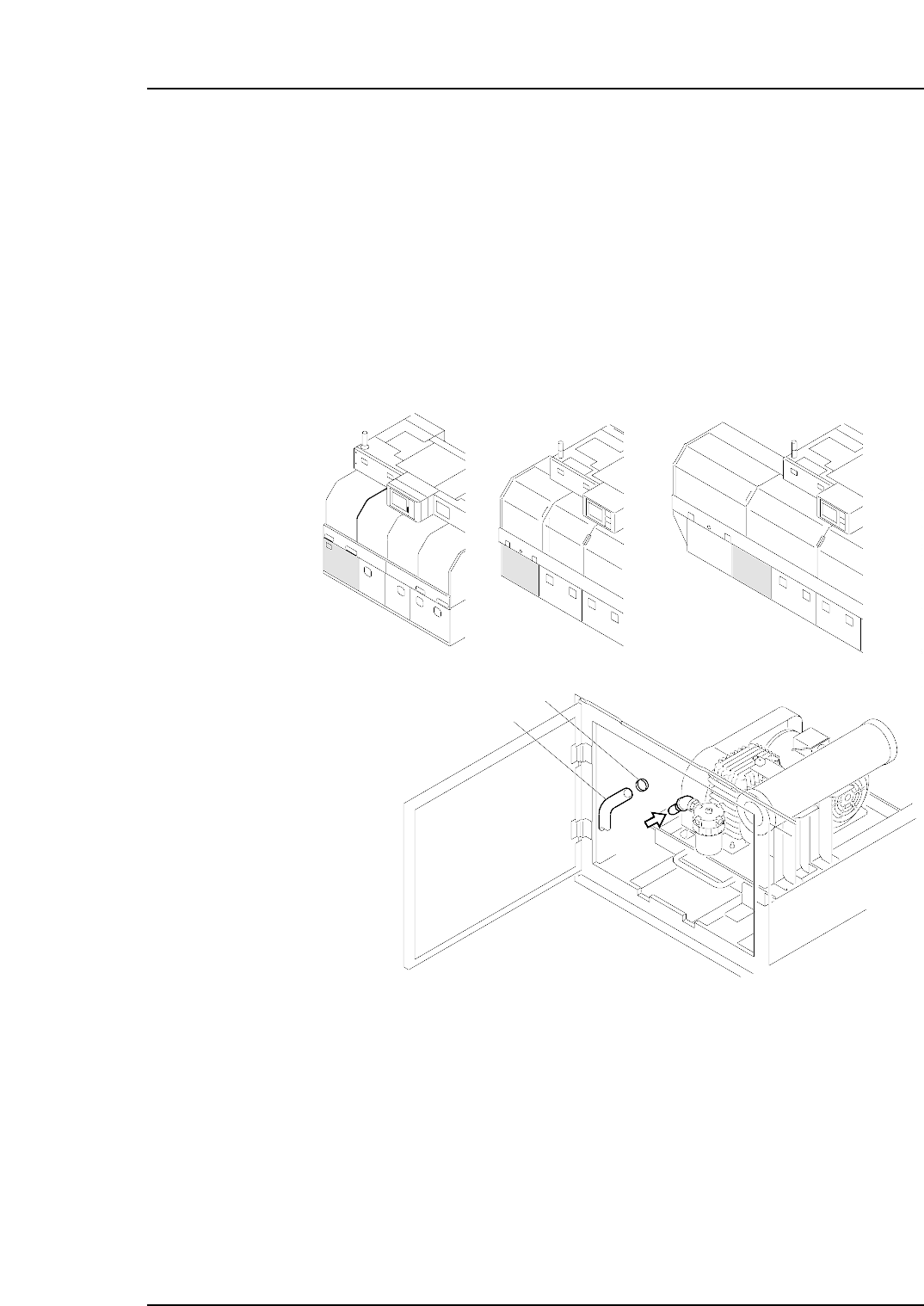
Checking the Three-phase Connections
Perform the following procedure to verify that the three-phases are properly connected.
1. Turn the 200V power on.
2 Log in the machine.
3. Press the [AUTO] button (but do not press START).
Note: Do not press the START button.
The vacuum pump begins operating when [AUTO] is pressed, so disconnect the
hose to verify that suction exists. If there is suction, this indicates that the wiring is
correct and the motor is rotating in the correct direction. If the air flow is reversed
(air is blowing out instead of in), then turn the main power off and reverse the three-
phase power cable’s U-phase and V-phase connections, then try again.
Caution: To avoid leaks, the hose should be pushed firmly into position, and then secured in
position with the hose band.
C7SM5005a
air
Hose
Hose band
<CP-742E><CP-732E> <CP-742ME>
Part 6 Chapter 3 Electrical Power Supply & Transformer Wiring
Edition 2.6 6-3-3 CP-7 series Mechanical Reference

Notes:
Part 6 Chapter 3 Electrical Power Supply & Transformer Wiring
Edition 2.6 6-3-4 CP-7 series Mechanical Reference
4. Connecting the Data Transmission Cable
Point
The machine is connected to the host computer by means of an Ethernet twisted-pair
communication cable (class 5) which permits program transmissions and production log
compilation.
Procedure
1. Register the CP-7-series machines in the line descriptor file at the host.
Note: Refer to the host computer manual for details regarding the registration procedure.
2. Connect one end of the transmission cable to the Ethernet connector at the host,
and connect the other end to the connector on the machine.
<CP-742E>
C7SM5006a
<CP-732E> <CP-742ME>
Part 6 Chapter 4 Connecting the Data Transmission Cable
Edition 2.3 6-4-1 CP-7-series Mechanical Reference