CP-7[732-742]-series Mechanical Reference(2.9E).pdf - 第171页
1.6.2 Sensor Amp Adjustment Open the front cover and follow the procedures below. 1. Check that the output dip switch is set to "L ON". 2. Set the power modes and timer modes as detailed below. 2-1. Press and h…
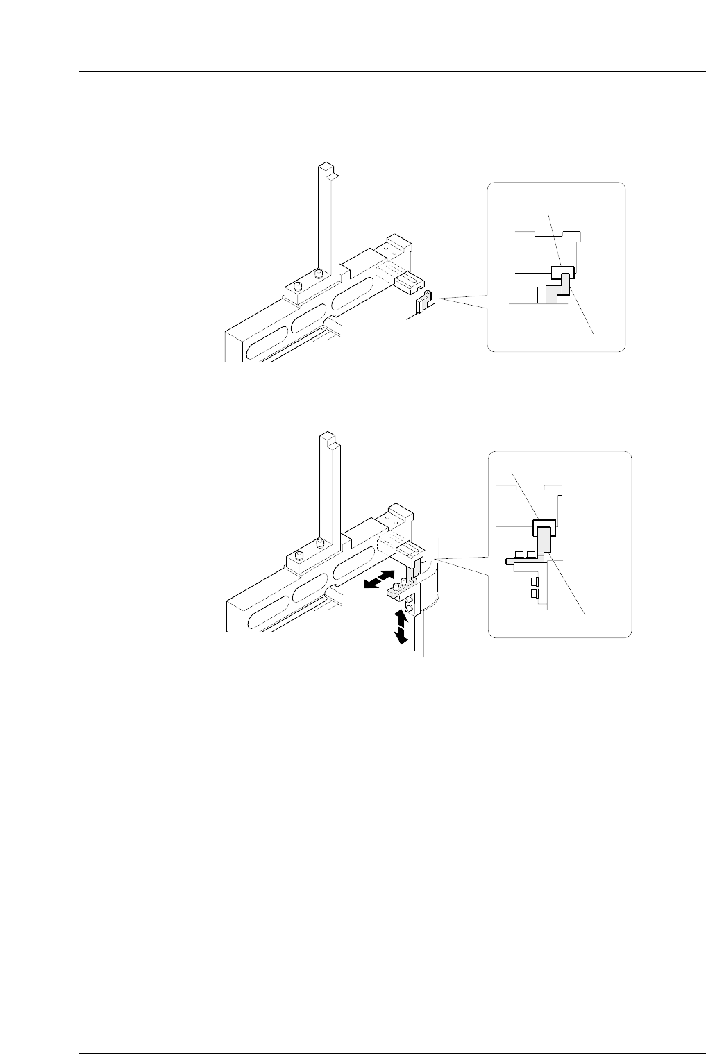
D1, D2 Retract Area (Lower direction check)
Inner sensor
Outer sensor
C7SM4053a
Block (DCPJ0070)
Sensor bracket
C7SM4052a
Block (DCPJ0060)
Sensor bracket
Part 4 Chapter 1 Station Adjustments
Edition 2.4 4-1-20 CP-7 series Mechanical Reference
1.6.2 Sensor Amp Adjustment
Open the front cover and follow the procedures below.
1. Check that the output dip switch is set to "L ON".
2. Set the power modes and timer modes as detailed below.
2-1. Press and hold down the MODE button for three seconds or more to change
the display to "turb".
Use the up and down arrow buttons to set the power mode to "SUPER".
2-2. Press the MODE button to change the display to "dLy".
Use the up and down arrow buttons to set the timer mode to OFF.
2-3. Press the MODE button again to return the display to the original state.
3. Press the MODE button to toggle the display from the light value, to the
percentage value (value + "P"), and then back to the light value.
Ensure that the figures for all the sensors are above the minimum values shown
below.
• CP-732E
Pickup area: 1000 digit (target: 2000 digit)
Retract area: 200 digit (target: 500 digit)
• CP-742ME
Pickup area: 1000 digit (target: 2000 digit)
Retract area: 100 digit (target: 300 digit)
• CP-742E
Pickup area: 1000 digit (target: 2000 digit)
Retract area: 30 digit (target: 100 digit)
Note: The sensor should be replaced when the light reading is at approximately 4095.
Check the following items if the light reading does not reach the minimum
required value.
a The position of the sensor bracket.
b Check that the sensor is correctly attached to the sensor bracket.
c The positioning of the fiber and attachment tips.
d Check whether the fiber and amp connections are correctly inserted.
e Check the condition of the fiber wiring.
SET
SUPER
TURBO
FINE
SET
40ms
10ms
OFF
MODE
D ON L ON
C7SM4023a
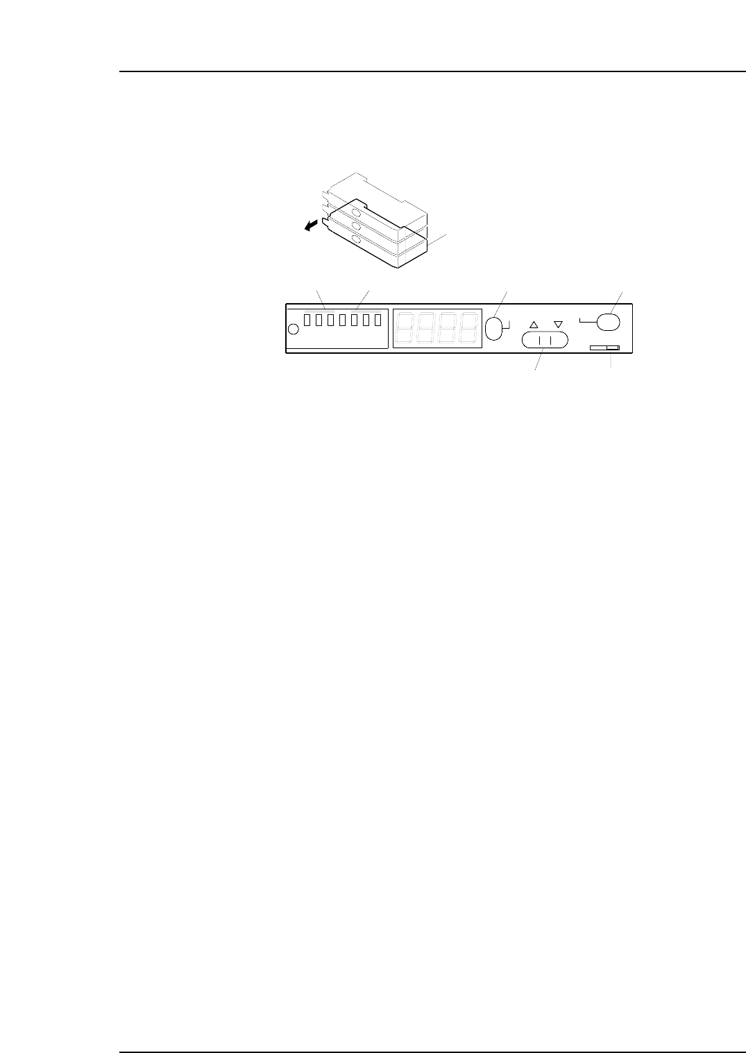
Feeder sensor amp
Output dip switch
[MODE] button[SET] button
[ ▼
•
▲ ]
button
Power mode Timer mode
Open the cover
Part 4 Chapter 1 Station Adjustments
Edition 2.4 4-1-21 CP-7 series Mechanical Reference

4. Change the display to show the percentage value by pressing the mode button to
toggle the display as required.
5. Use the up and down arrow buttons to set the value to 200 where no object
interrupts the sensor.
Note: The arrow buttons cannot be used if the display reads 999P. In this situation, press
the SET button twice to revert the display to 100P.
Part 4 Chapter 1 Station Adjustments
Edition 2.4 4-1-22 CP-7 series Mechanical Reference