CP-7[732-742]-series Mechanical Reference(2.9E).pdf - 第215页
Notes: Part 5 Chapter 1 Troubleshooting T able Edition 2.7 5-1-12 CP-7 series Mechanical Reference
1.6 Part Height Sensor Errors
No.
6-1
6-2
6-3
6-4
M: Part 3
Chapt 1 "1.8"
M: Part 3
Chapt 1 "1.4"
M: Part 3
Chapt 3 "3.1"
T: Part 3
Lesson 2
"2.1.1"
U: Part 2
Chapt 4
"Appearance"
T: Part 3
Lesson 2
"2.1.1"
Nozzle length
warning
displays
Replace the nozzle where this warning
occurs, then easure the nozzle length
again.
If the measured nozzle length exceeds the
permissible value, a warning displays
onscreen.
This error occurs when dust has adhered to
the part height sensor's camera lens.
Automatic operation continues unless the
quantity of dust is such that it hinders the
measurements.
Note: Clean away the dust using cotton
swab, etc.
Error occurs because the Part data setting
differs from the height of the part which was
picked up.
Error occurs because an unsuitable part
height tolerance value is specified in Part
data. The tolerance value varies according
to the part type. Verify that the tolerance
value is appropriate for the part in question.
(Refer to the tolerance values recommended
by Fuji.)
A part may be picked up in a tombstoned
posture if the nozzle length measurement
result differs from the actual nozzle length
When using part height information, measure
the nozzle length before production begins.
A bent nozzle will cause a deviation in the
part pickup position, and may result in the
part being picked up in a tombstoned
posture.
A stuck nozzle cannot adequately reach the
part, and may result in the part being picked
up in a tombstoned posture.
A clogged nozzle will have less vacuum
force, and may result in the part being
picked up in a tombstoned posture.
A malfunctioning "acquisition timing" sensor
can cause the 7-segment display to always
show the same value, or to show the wrong
value.
Note: If sensor replacement is required,
contact your Fuji agent for assistance.
Clean the glass surface of the part
height sensor.
Dust alarm
(dust detected
on part height
sensor)
Part
tombstoning
detection error
The 7-segment
display always
shows the same
value, or shows
the wrong value.
Cause Remedy Remarks Ref. Page
Check the height of the part where the
error occurred, and enter the correct
setting value.
Check the part height tolerance value
(%) for the part where the error ocurred,
and enter the correct setting value.
Use the nozzle check command to
perform a nozzle length measurement.
Replace the nozzle if its length is outside
the tolerance range.
(1) Use the nozzle check command to
check for a bent nozzle.
(2) Press the reflective disk with your
finger to verify that the nozzle spring-
back motion is smooth.
(3) Check for a clogged nozzle.
Replace the nozzle if any of the above
problems are found.
Turn the cam handle and check the LED
lamp status on the sensor (for
acquisition timing) inside the cam box.
If there is a problem with the sensor,
replace it.
Part 5 Chapter 1 Troubleshooting Table
Edition 2.7 5-1-11 CP-7 series Mechanical Reference

Notes:
Part 5 Chapter 1 Troubleshooting Table
Edition 2.7 5-1-12 CP-7 series Mechanical Reference
2. Servo System Troubleshooting
An AC servo system controls all servo axes in the machine. If there is a problem with the servo
system, the machine displays an alarm code to notify the operator.
This section describes alarm codes and inspection methods, and should be used as a reference for
troubleshooting and resolving problems.
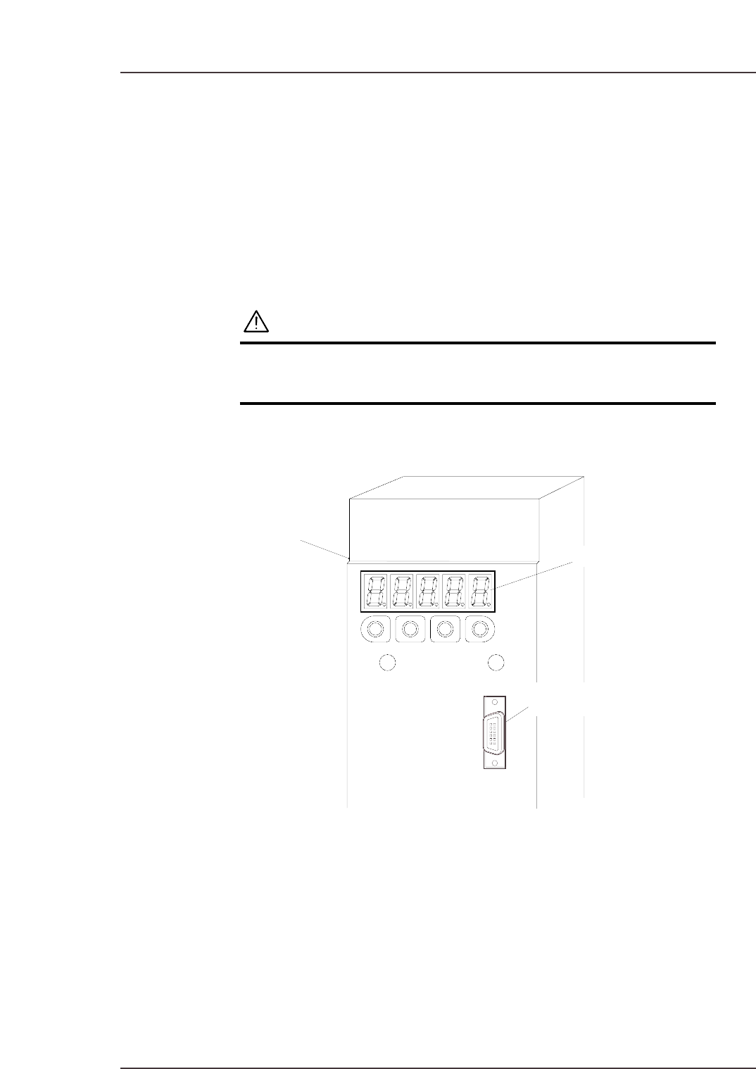
2.1 Alarm Code Display
Each servo amp has an LED panel to display alarm codes.
The following illustrations show the location of each servo amplifier’s LED panel.
WARNING
The servo amplifier power terminal is high voltage.
Absolutely do not touch the servo amplifier power
terminal.
Note: To display the alarm code on the digital operator, connect the digital operator cable to the
servo amplifier (CN3 connector).
C7SM6001E
Servo amplifier
LED panel
Connector (CN3)
Part 5 Chapter 2 Servo System Troubleshooting
Edition 2.6 5-2-1 CP-7 series Mechanical Reference