CP-7[732-742]-series Mechanical Reference(2.9E).pdf - 第187页
1.12 Reverse-theta Mechanism (Station 10) Point This mechanism reverses the nozzle rotation which occurred at the station 9 part placement. The nozzle is returned from that part placement angle by the amount of rotation …
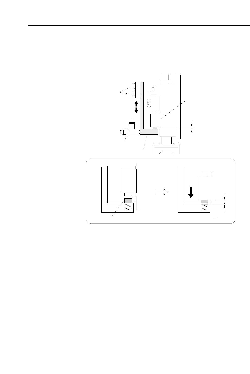
4. Loosen the mounting bolts shown in the figure below, then adjust the lever height
until there is a 1.9 mm gap (use a thickness gauge) between the bottom of the
mechanical valve and the lever. At this stage, the spring pusher is pressed down
0.1 mm.
Note: Do not touch the speed regulator.
The blow air pressure is set to 15.0 ± 0.5 kPa (13st: 7.0 ± 0.5 kPa). The user should not
change the setting, as a manometer is required for the adjustment.
Lever
Pusher
1.9 mm
0.1 mm
Mounting bolts
Mechanical valve
Speed regulator
C7SM4037a
1.9 mm
Part 4 Chapter 1 Station Adjustments
Edition 2.4 4-1-36 CP-7 series Mechanical Reference
1.12 Reverse-theta Mechanism (Station 10)
Point
This mechanism reverses the nozzle rotation which occurred at the station 9 part
placement. The nozzle is returned from that part placement angle by the amount of
rotation which occurred at stations 2 and 8.
1.12.1 Clutch Meshing Check
Perform this check on the low-pressure nozzle.
Note: The low-pressure nozzle refers to the placing head (out of the 16) that receives the weakest
pushing pressure. Use the low-pressure nozzle for meshing checks at stations 2, 8 and 10.
1. Press the EMERGENCY STOP button to take the 200V down to 100V.
WARNING
• Always be sure to cut off the 200V power before carrying
out any work.
• Exercise extreme caution when working on the machine if
the cam is not at its origin (0 deg.). Recoil of the cam
axis can endanger the operator.
2. Set the cam angle to 0 degrees, then turn the station 10 solenoid valve on to work
the cam lever.
3. Set the dial gauge to the bottom of the nozzle shaft brake.
4. Use the cam handle to rotate the cam to 200°.
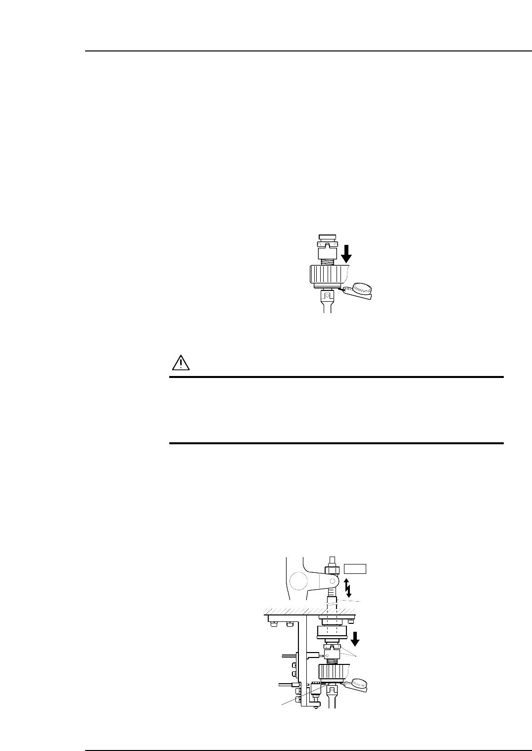
5. Ensure that the clutches mesh properly and the placing head assembly deflects the
dial gauge by 0.30 ~ 0.35 mm as illustrated below.
Clutch
10st
Rod
0.30~0.35 mm
C7SM4038a
Measure the amount
of push down
Nozzle shaft brake
Measure the pushing pressure
at all nozzles to determine the
lowest value.
C7SM4058
Part 4 Chapter 1 Station Adjustments
Edition 2.4 4-1-37 CP-7 series Mechanical Reference
1.12.2 Clutch Meshing Check Sensor Position Adjustment
1. Press the EMERGENCY STOP button to take the 200V down to 100V.
WARNING
• Always be sure to cut off the 200V power before carrying
out any work.
• Exercise extreme caution when working on the machine if
the cam is not at its origin (0 deg.). Recoil of the cam
axis can endanger the operator.
2. Use the cam handle to rotate the cam to 200°.
3. Execute inching to align the RQ-axis with the RQ-data position.
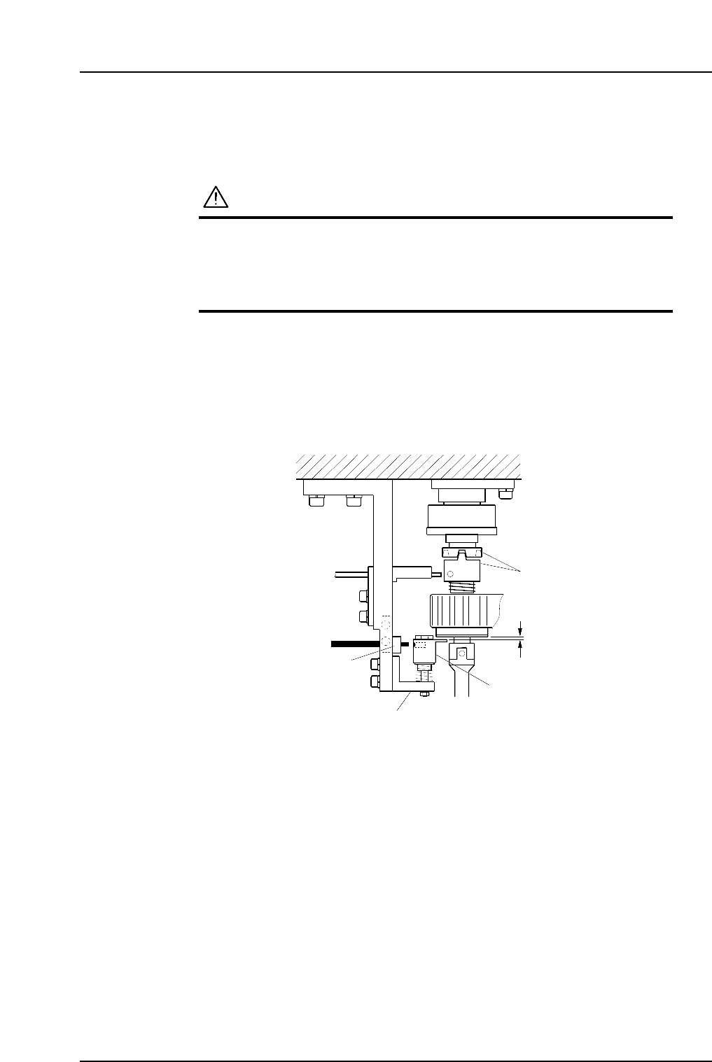
4. Make sure the clutches engage properly. Adjust the height of Bracket A so that
Gap C in the figure is 0.2 mm.
5. At this position, adjust the position of Bracket B so that the sensor beam hits the
hole on the dog.
Dog
Clutch
Bracket A
Bracket B
C7SM4039a
0.2 mm
C
Part 4 Chapter 1 Station Adjustments
Edition 2.4 4-1-38 CP-7 series Mechanical Reference