CP-7[732-742]-series Mechanical Reference(2.9E).pdf - 第138页
3.9 Replacing the V acuum Pump Motor Procedure W ARNING • Be sure to switch off the 200V power supply before beginning this procedure. • Do not touch the vacuum pump immediately after operation as it may be extremely not…
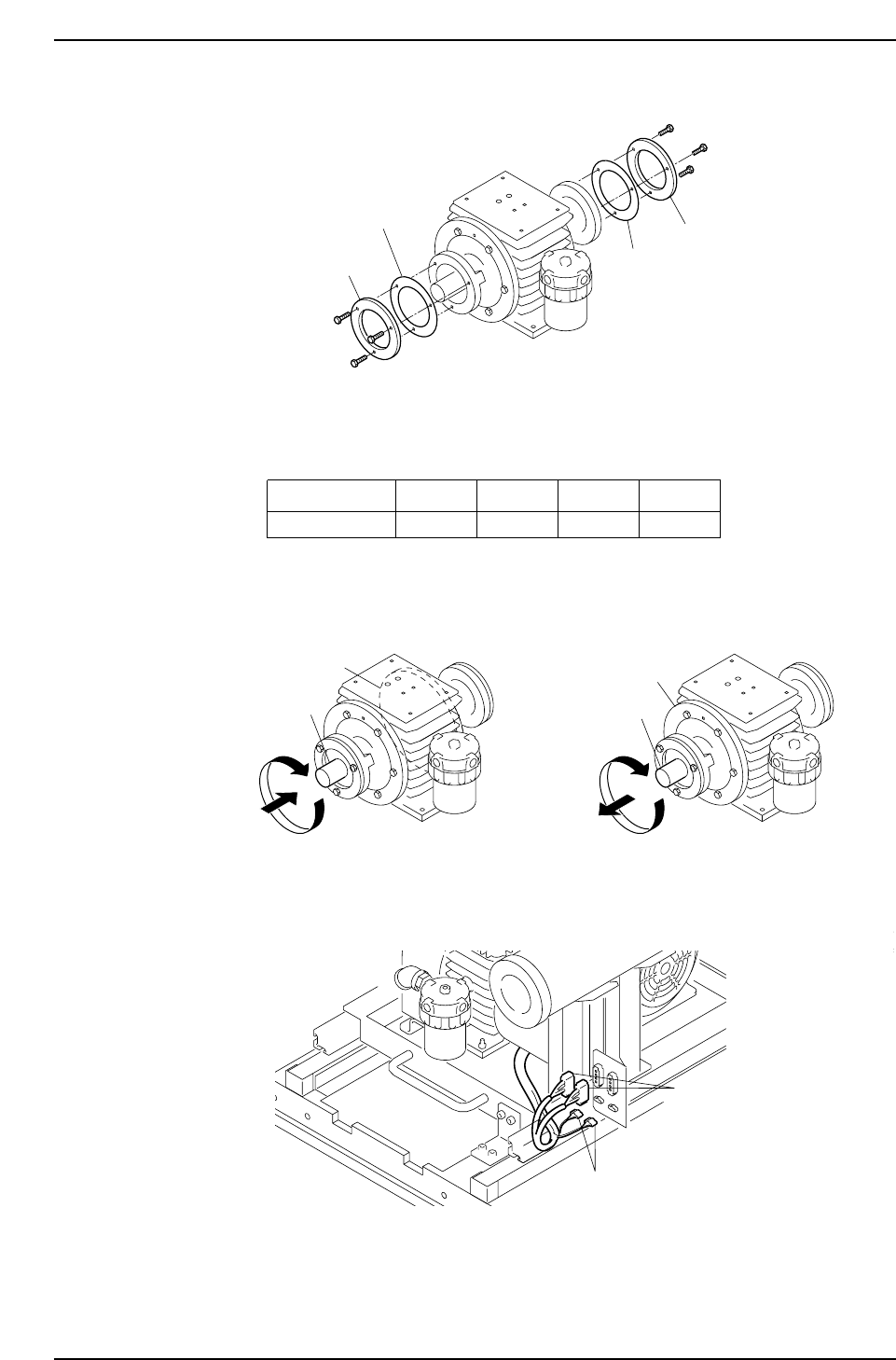
7. Place the liners and bearing retainers on side plates "A" and "B".
Note: Even if the number of liners and their combinations are assembled in the same
manner as when disassembled, there may be some looseness when the shaft
rotates. The number of liners and the liner thickness should therefore be adjusted as
necessary to eliminate this looseness.
8. Verify that there is no contact between the rotor and the side plates when the rotor
is rotated while pushing and pulling the rotor shaft.
9. Complete the vacuum pump reassembly by reversing steps 1 to 6 of the
disassembly procedure, then reconnect the harness connectors.
Conectors
Conectors
C7SM3062E
C7SM3080E
Side plate A
Side plate B
Shaft
Shaft
C7SM3079E
Liner Thickness
Color Coded
0.03 mm
Red
0.05 mm
Yellow
0.10 mm
Black
0.20 mm
No color
C7SM3068E
Bearing retainer
Bearing retainer
Liner
Liner
Part 3 Chapter 3 Replacing Consumable Parts
Edition 2.7 3-3-18 CP-7 series Mechanical Reference
3.9 Replacing the Vacuum Pump Motor
Procedure
WARNING
• Be sure to switch off the 200V power supply before
beginning this procedure.
• Do not touch the vacuum pump immediately after
operation as it may be extremely not. Allow the
pump to cool before performing this procedure.
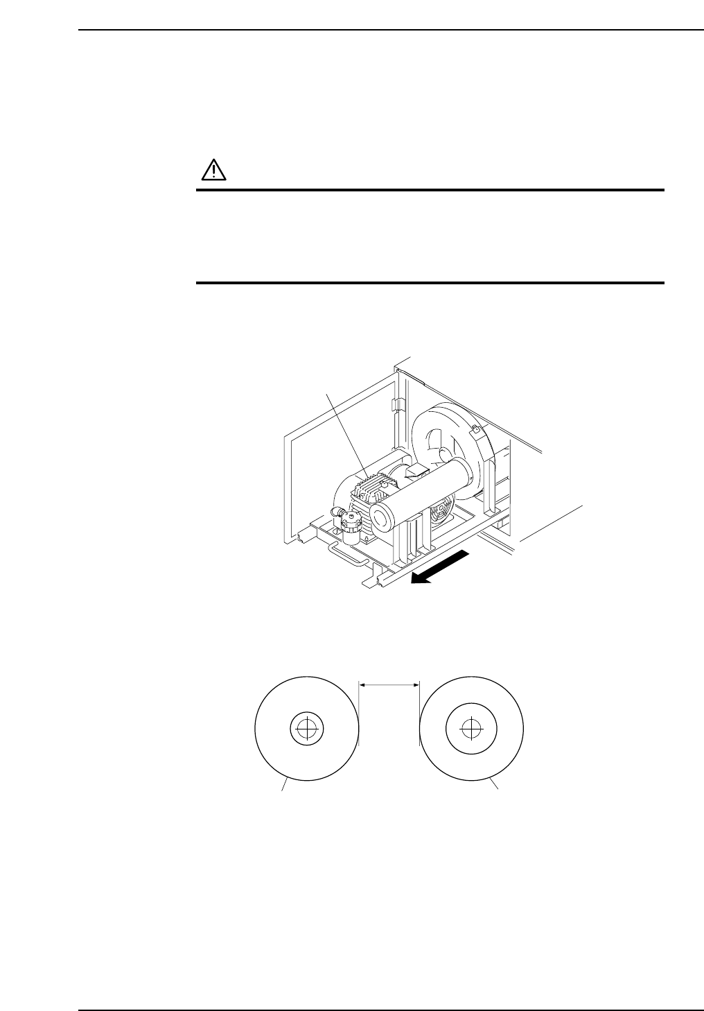
1. Pull out the vacuum pump. (For this procedure, refer to section 3.7 "Replacing the
Vacuum Pump Belt").
2. Use calipers to measure the distance between the vacuum pump pulley and the
motor pulley, and make a note of this measured value.
C7SM3081E
L
Motor pulley
Vacuum pump pulley
Vacuum pump
C7SM3056E
Part 3 Chapter 3 Replacing Consumable Parts
Edition 2.7 3-3-19 CP-7 series Mechanical Reference
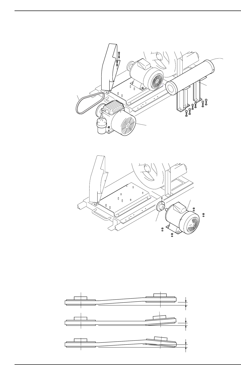
3. Remove all parts which hinder the motor replacement work. These parts include
the vacuum pump, duct, the belt.
4. Remove the motor, then remove the pulley from the motor.
5. Mount the pulley on the new motor, then set the motor and vacuum pump on the
base. Bolts which secure the pulley, motor, and vacuum pump should only be
partially tightened at this time.
Final tightening should be performed after adjusting the pulley deviation and the
distance between the vacuum pump pulley and motor pulley (distance noted at
step 2). The pulley deviation should be 0.3 mm or less.
C7SM3082E
Reference-side pulley
0.3 mm or less
0.3 mm or less
0.3 mm or less
C7SM3061E
Pulley
Motor
C7SM3060E
Duct
Vacuum pump
Belt
Part 3 Chapter 3 Replacing Consumable Parts
Edition 2.7 3-3-20 CP-7 series Mechanical Reference