00196624-04_Service Manual WPC5_6_EN_01-2019.pdf - 第119页
Service Ma nual W PC5 / WPC6 4.1.4 Calibrating the Limit Switch The plus and min us posi tion of t he li mit sw itch es need to b e calibr ate d. ➢ Remove al l waffle-pack tray c arriers (WPTC) from the WPC. ➢ Select the…
Service Manual WPC5 / WPC6
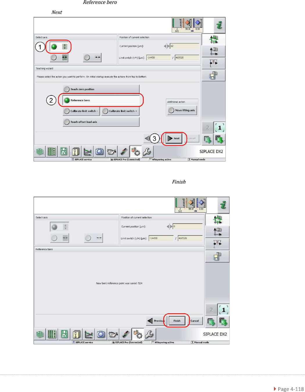
4.1.3 Reference Proximity Switch (Bero)
➢ Remove all waffle-pack tray carriers (WPTC) from the WPC.
➢ Select the lifting axis (1).
➢ Select the function (2).
➢ Select (3).
➢ Confirm the new reference point proximity switch with .
Service Manual WPC5 / WPC6
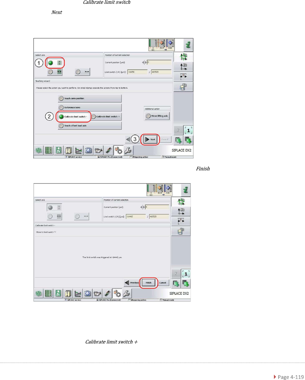
4.1.4 Calibrating the Limit Switch
The plus and minus position of the limit switches need to be calibrated.
➢ Remove all waffle-pack tray carriers (WPTC) from the WPC.
➢ Select the lifting axis (1).
➢ Select the function - (2).
➢ Select (3).
Calibrating the limit switch -
➢ Confirm the new position at which the limit switch triggers with .
Calibrating the limit switch +
➢ Select the lifting axis (1).
➢ Select the function and continue with the same procedure as that
used for calibrating the limit switch.
Service Manual WPC5 / WPC6
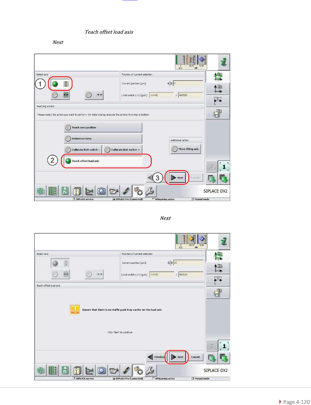
4.1.5 Teaching the Load Axis Offset Point
You only need to teach the offset point if you have changed the zero point position (see "4.1.2
Teaching the Zero Point Position" [
➙
4-115]).
➢ Remove all waffle-pack tray carriers (WPTC) from the WPC.
➢ Select the lifting axis (1).
➢ Select the function (2).
➢ Select (3).
➢ Follow the instruction shown and continue with .