TRS Advanced WB Intel Issue 02.pdf - 第19页
Issue 2, Nov 14 TRS Advanced Maintenance 19 12. Adjust the angle of the cylinder to achieve a 1mm – 2mm gap between the flow controller on the cylinder and t he pantograph spring bracket. NOTE Check the gap, once springs…
TRS Advanced Maintenance
18
Issue 2, Nov 14
Use the following procedure to remove and replace the TRA cylinders.
1. Ensure Rising Table and TRP are at their Home positions.
2. Power down the machine and disconnect the air supply
3. When removing the cylinders the TRP arms may lift. Hold the TRP down and secure
with cable ties.
4. Cut all cable ties connecting the pneumatic tubes and sensor wires to the cylinder.
5. Disconnect all pneumatic tubes from the 4 x flow controllers per cylinder
6. Disconnect the 2 x pantograph springs per side by removing L Bracket from the sliding
block. Do Not Use Pliers
7. Remove sensors and straps from Left Hand cylinder. It is not necessary to unplug the
sensors from the electrical interface bracket. If this is done ensure loom / connectors
are clearly labelled.
8. Remove the M8 nuts from the tip of the cylinder rods. Note: these nuts are secured
with ‘Green’ thread lock compound so maybe tight. These nuts will not be required
when fitting the new cylinder as new nuts are provided.
9. Remove the M20 nuts from the fixed end of the cylinder. Note: these nuts are secured
with ‘Blue’ thread lock compound. These nuts will not be required when fitting the new
cylinder as new nuts are provided. Note: Using another spanner on the flat section of
the cylinder can hold the cylinder still whilst these nuts are loosened and removed.
10. Remove the cylinder from the TRS assembly.
11. Fit the new cylinder between the brackets. Fit the M20 nut using ‘Blue’ thread lock
compound. Do not fully tighten the nut at this stage.
Issue 2, Nov 14
TRS Advanced Maintenance
19
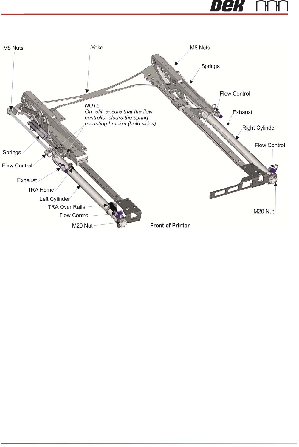
12. Adjust the angle of the cylinder to achieve a 1mm – 2mm gap between the flow
controller on the cylinder and the pantograph spring bracket.
NOTE
Check the gap, once springs are fitted.
13. Tighten the M20 nut maintaining the 1mm – 2mm gap set above.
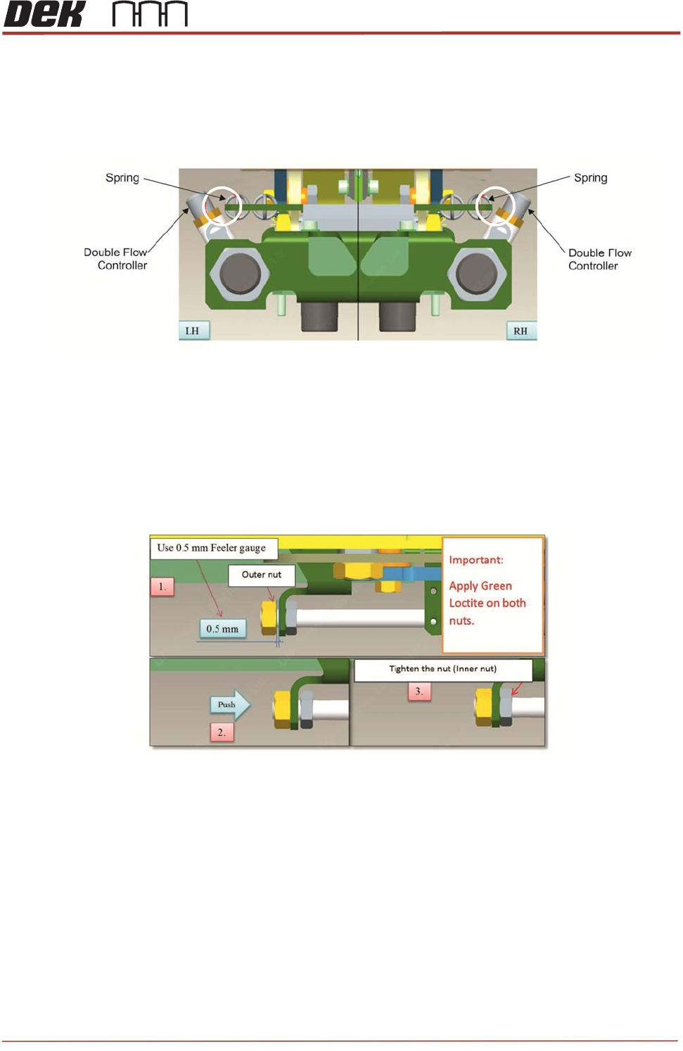
14. Ensure ‘Green’ thread lock compound is used on both outer and inner M8 nuts.
15. Ensure the TRP arms are fully down and pushed towards the rear of the machine
whilst completing the below. Ideally another person should be used to hold the TRP
arms in position.
16. Place a 0.5mm feeler gauge between the outside M8 nut and the bracket and tighten
the nut, this will draw the cylinder out to its full extent.
17. Once complete, remove the feeler gauge and push the cylinder back in closing the
0.5mm gap between the outer nut and the bracket.
18. Wind the inner nut to tighten against the inside of the bracket.
19. Confirm TRA will run to the solid stop points (Dowel Pin).
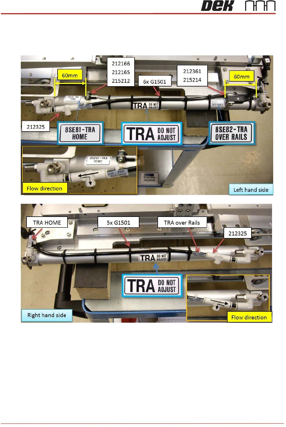
20. Refit pneumatic tubes. Double check exhaust valves are fitted in correct orientation
(use arrow on valve body – should be away from cylinder).
TRS Advanced Maintenance
20
Issue 2, Nov 14
21. Secure tubing (and sensor cables on left side) with 6 off cable ties – ensure tubes are
not pinched / crushed.
22. On left hand cylinder set the two sensors approx. 60mm from each end of the cylinder.
This will be checked / adjusted once machine is powered up.
23. Refit the pantograph springs.
NOTE
Spring damage can occur if users overstretch the springs when fitting them to the
assembly: this may cause fatigue and accelerate premature failure. Do not use pliers
to aid fitment.