TRS Advanced WB Intel Issue 02.pdf - 第20页
TRS Advanced Maintenance 20 Issue 2, Nov 14 21. Secure tubing (and sensor cables on left si de) with 6 off cable ti es – ensure tubes are not pinched / crushed. 22. On left hand cylinder set the two sensors approx. 60mm …
Issue 2, Nov 14
TRS Advanced Maintenance
19
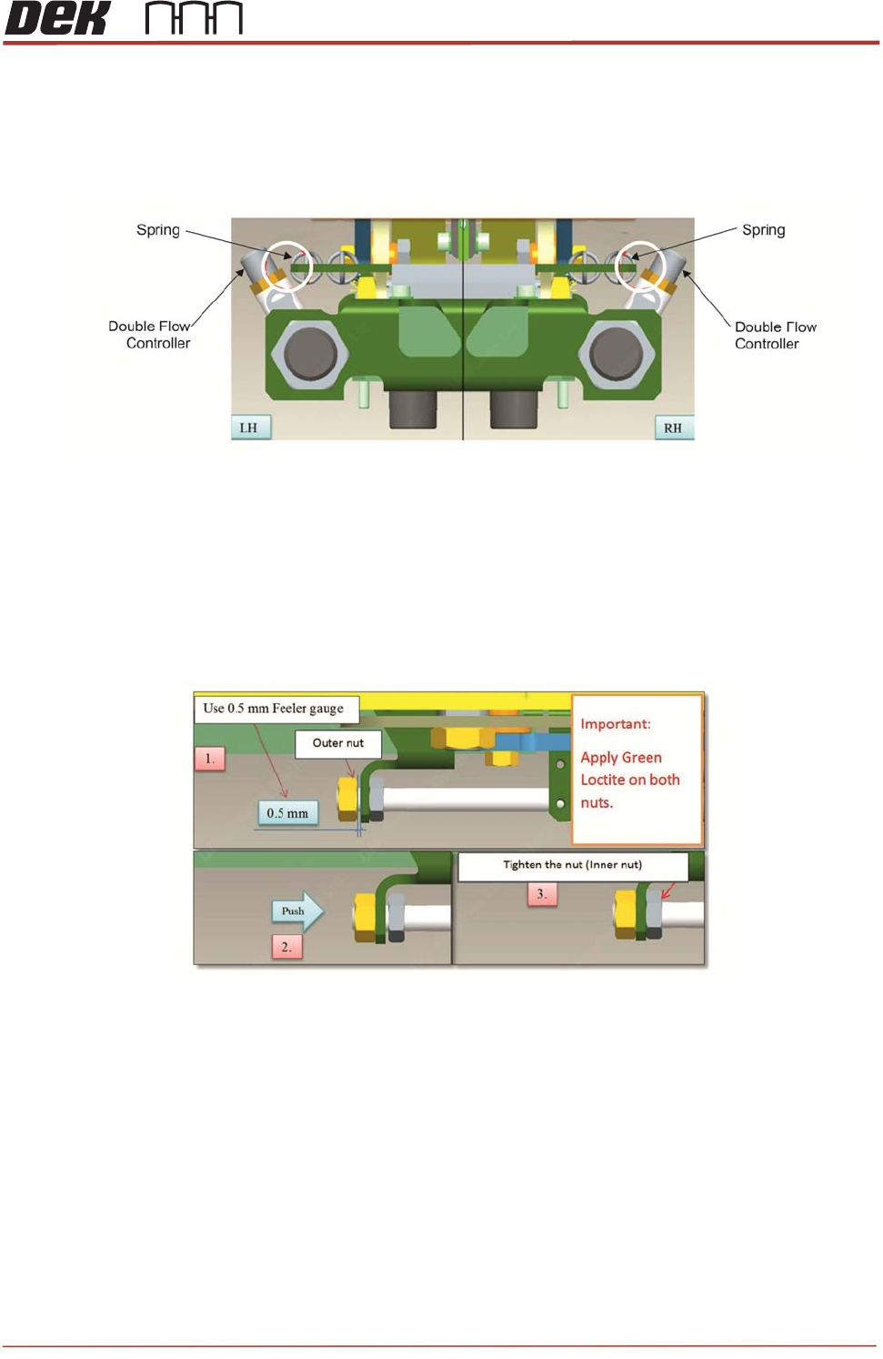
12. Adjust the angle of the cylinder to achieve a 1mm – 2mm gap between the flow
controller on the cylinder and the pantograph spring bracket.
NOTE
Check the gap, once springs are fitted.
13. Tighten the M20 nut maintaining the 1mm – 2mm gap set above.
14. Ensure ‘Green’ thread lock compound is used on both outer and inner M8 nuts.
15. Ensure the TRP arms are fully down and pushed towards the rear of the machine
whilst completing the below. Ideally another person should be used to hold the TRP
arms in position.
16. Place a 0.5mm feeler gauge between the outside M8 nut and the bracket and tighten
the nut, this will draw the cylinder out to its full extent.
17. Once complete, remove the feeler gauge and push the cylinder back in closing the
0.5mm gap between the outer nut and the bracket.
18. Wind the inner nut to tighten against the inside of the bracket.
19. Confirm TRA will run to the solid stop points (Dowel Pin).
20. Refit pneumatic tubes. Double check exhaust valves are fitted in correct orientation
(use arrow on valve body – should be away from cylinder).
TRS Advanced Maintenance
20
Issue 2, Nov 14
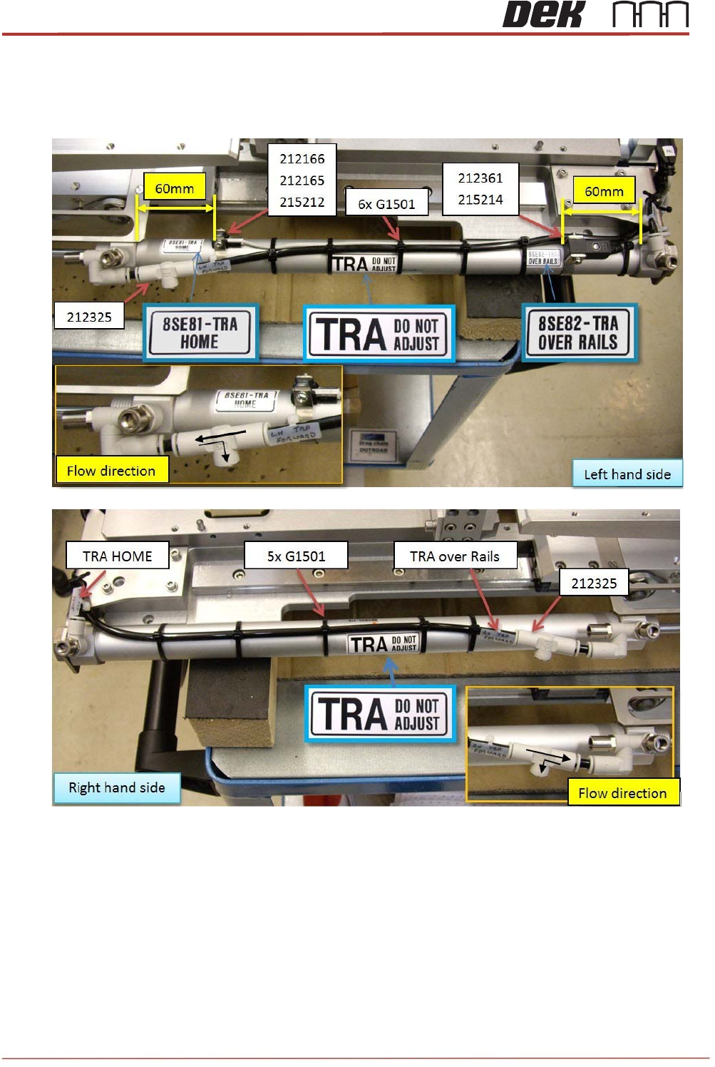
21. Secure tubing (and sensor cables on left side) with 6 off cable ties – ensure tubes are
not pinched / crushed.
22. On left hand cylinder set the two sensors approx. 60mm from each end of the cylinder.
This will be checked / adjusted once machine is powered up.
23. Refit the pantograph springs.
NOTE
Spring damage can occur if users overstretch the springs when fitting them to the
assembly: this may cause fatigue and accelerate premature failure. Do not use pliers
to aid fitment.
Issue 2, Nov 14
TRS Advanced Maintenance
21
TRA Cylinder Tuning:
Reconnect the air to the machine, power up and enter diagnostics. Make fine adjustments to
the two sensor positions. Move the TRA as required to the trigger points.
• Home position.
• Over rails position (not pressured down). Ensure the sensor is positioned to trigger on
at this point and remain on while the TRA is pressured and the rising table translates
to vision height.
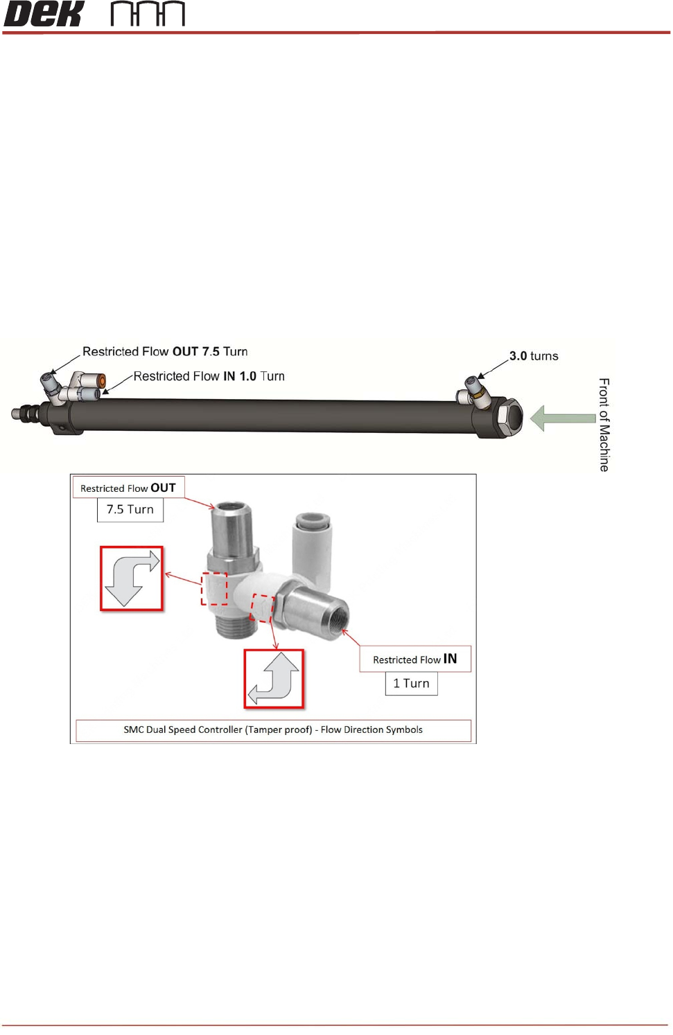
The flow control adjustment features are factory set to zero and require further adjustment.
Set the flow controllers using the special tool (212511). The required positions are as follows:
TRA (Left & Right) - Front (Out) = 3.0 turns from closed position.
TRA (Left & Right) - Rear(In) = 1.0 turn from closed position.
TRA (Left & Right) - Rear(Out) = 7.5 turns from closed position.
Apply a small dot of Varnistop Loctite 7400 to confirm setting has been done.
Cycle the TRP a few times to check consistent sensor operation and that Left Hand and
Right cylinders operate together (same speed), if not adjust Sensor position or flow
controllers.
NOTE
Cycle the TRA a few minutes to confirm there are no timing issues relating from speed,
sensor positioning or the function of the cylinders.
Observe the sensor states and confirm they are switching on at the over rails position and
home position.