TRS Advanced WB Intel Issue 02.pdf - 第24页
TRS Advanced Maintenance 24 Issue 2, Nov 14 Objective 11: Replace TRA Interlock Pins The Interlock pins can be found on the TRA slider body. Their purpose is to prevent the TRP from lifting too high, bef ore the plate is…
Issue 2,
3.
w
N
D
4.
T
s
5.
T
Note
s
Nu
t
to
1
Nov 14
Rotate th
e
w
ashers c
NOT
E
D
o not ap
p
T
ighten th
e
s
hould re
m
T
est the T
s
:
t
tightened
1
0Nm
e
pins app
r
ontact the
p
ly any Lo
c
e
nuts wit
h
m
ain close
RP move
m
oximately
bar.
c
tite.
h
a 17mm
to flush w
i
m
ent to en
s
¼ turn ba
c
spanner (
1
i
th the top
s
ure corre
c
c
k down a
n
1
0Nm). T
h
of the bar
.
c
t operati
o
+/‐0.
5
Toto
p
Spri
n
Dow
n
T
R
n
d wind th
e
e pins ma
y
.
No furthe
n of the S
t
5
mm
p
surface
n
gEnd
n
ward
R
S Advanc
e
e
nuts up
s
y
spin up
a
e
r adjustm
e
t
ripper Pin
s
e
d Maintena
2
3
s
o that the
a
little, but
e
nt is requ
i
s
.
nce
3
i
red.
TRS Advanced Maintenance
24
Issue 2, Nov 14
Objective 11: Replace TRA Interlock Pins
The Interlock pins can be found on the TRA slider body. Their purpose is to prevent the TRP
from lifting too high, before the plate is homed.(See Technical Reference Manual)
Locate the two Interlock pins on the machine. Discuss the operation of the Interlock pins with
your Instructor.
Remove and Replace the Interlock Pins.
Preparation:
1. Remove TRP and home the arm assembly.
2. Home rising table and power down printer.
3. Open cover and remove front access panel.
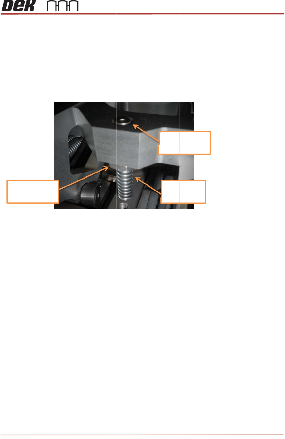
4. Locate the two interlock locations within the slider bodies.
5. Remove the two countersunk screws that are directly above the interlock caps.
6. Clean inside of the main bore and inside the brass bushing to remove any debris or
dust.
7. Discard all removed components.
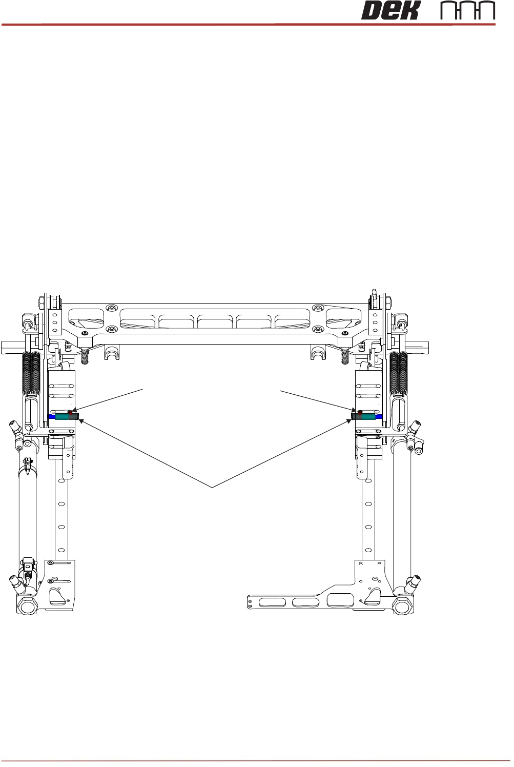
Interlock Pin Assemblies
M3x5 Countersunk Head Screws
Issue 2, Nov 14
TRS Advanced Maintenance
25
Replacement:
8. Place a loose spring (212100) over each of the partial interlock assemblies. Insert the
assembly and spring into the empty bore. Confirm that the cap and pin slide freely in
their respective bores.
9. Push in the caps and confirm the springs push them back out again.
10. Hold in the caps. Push in the pins and confirm the springs push them back out again.
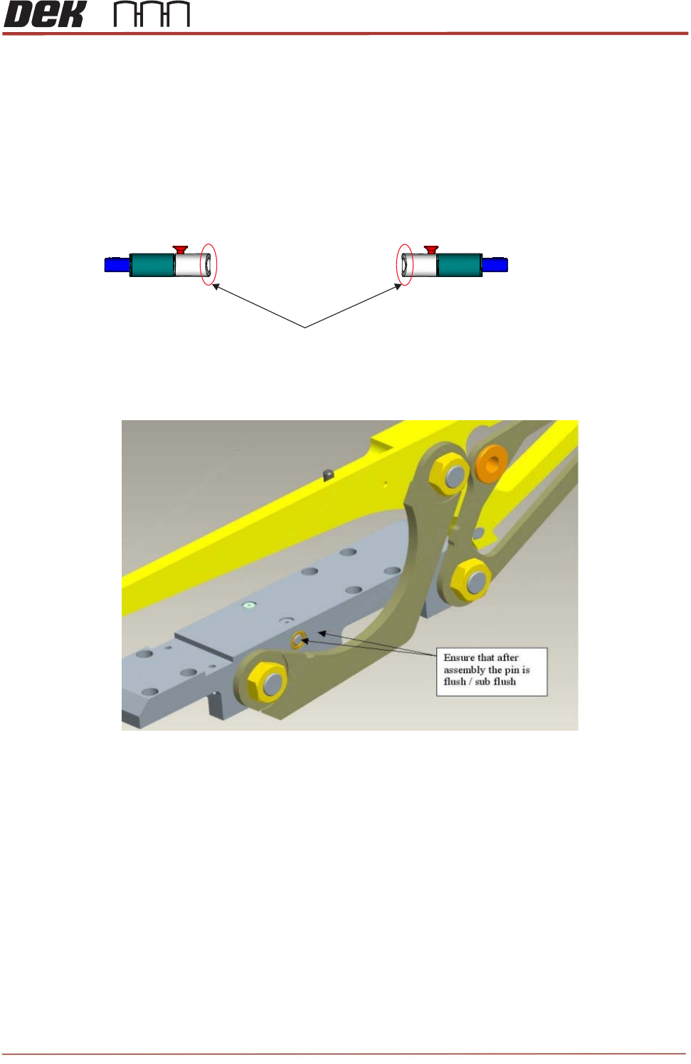
11. Orient the caps so that the chamfered edge is nearest the front of the machine.
12. Check that after assembly the pin is flush with the edge of sliding body.
13. Secure the caps with the two small countersunk screws (212408). Apply a small
amount of Pink Loctite 222 (113275) and allow some time to dry.
14. Confirm free motion of the caps and springs with the screws in place.
15. Re-mount the front access panel, close cover and initialize machine.
16. Drive TRA to over rails position and load a TRP.
17. Drive to pressure and vision height.
18. Home the TRP and observe its motion. If the TRP lifts unevenly or to more than
10mm, there may be an outstanding problem with the interlock function. Re-check for
free movement of the caps and pins.
Chamfered edge is facing the front of the machine