TRS Advanced WB Intel Issue 02.pdf - 第67页
Issue 2, Nov 14 TRS Advanced Maintenance 67 86. Connect the loom from t he rear rail home sensor mark ed 8PL231 to the sockets on the interface bracket as shown below. 87. The loom must sit between the pneumatic pipes an…
TRS Advanced Maintenance
66
Issue 2, Nov 14
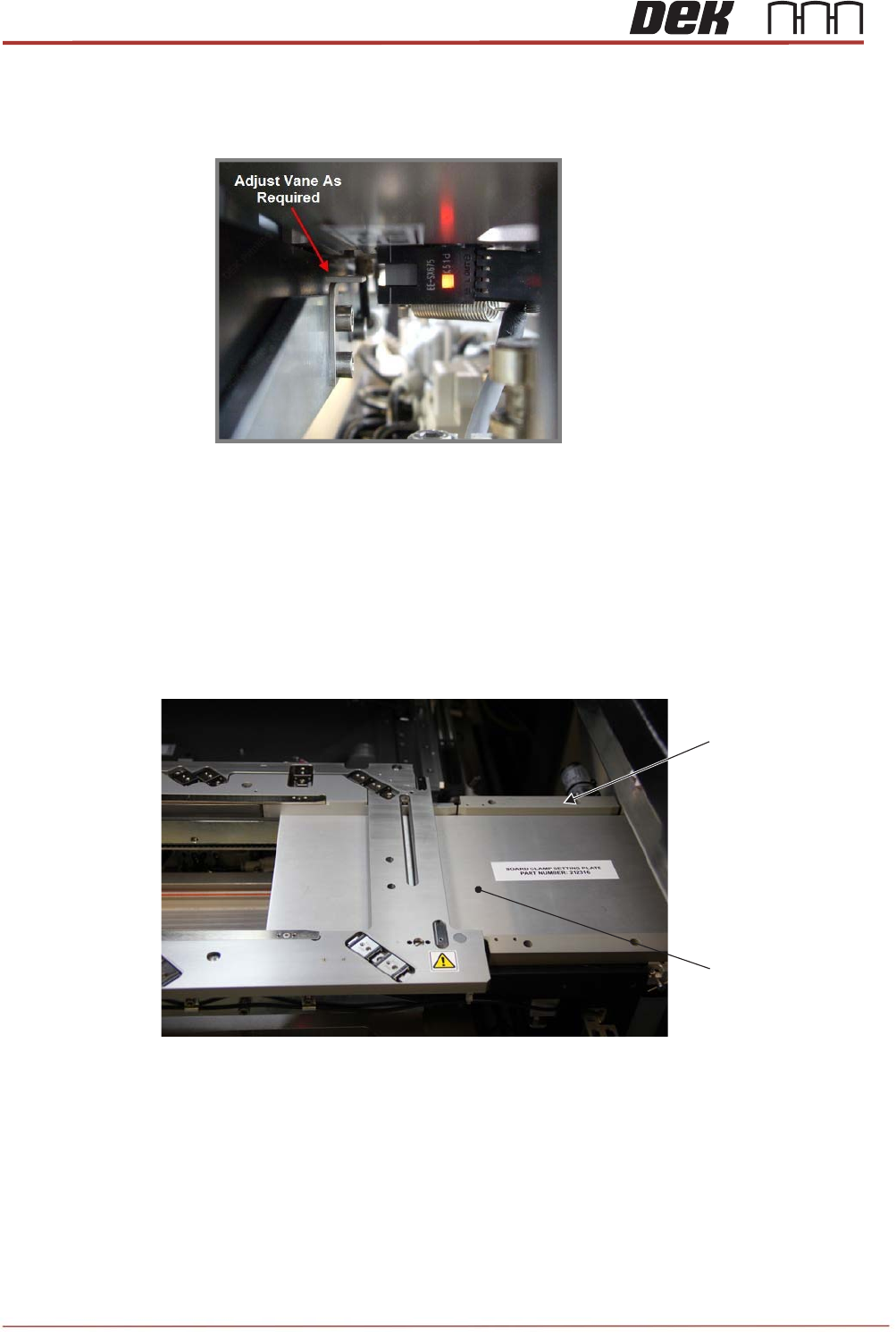
82. Check & adjust the height of the rail at tooling vane (RAT vane) to ensure the vane
will pass in / out sensor correctly.
83. Remove the height setting pins from under the rail cap before manually moving the
moving rail to home.
84. Re-fit the transport rail belts to the front and rear rails.
85. Slide the board clamp setting plate (212316) onto the transport rails and push the
guides to the plate to set the parallelism and tighten the screws. Repeat for the left
side.
Right Side Rear Rail
Centre Belt Guide
(4 Positions)
Board Clamp Setting
Plate
View on Right Side of the Printer
Issue 2, Nov 14
TRS Advanced Maintenance
67
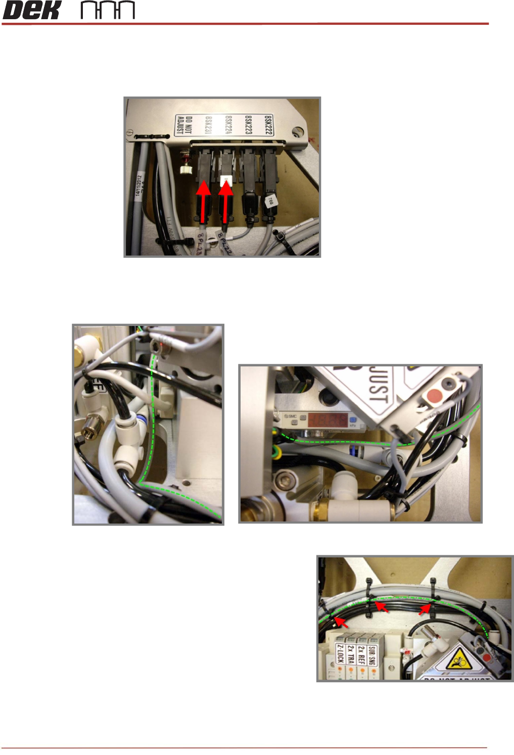
86. Connect the loom from the rear rail home sensor marked 8PL231 to the sockets on
the interface bracket as shown below.
87. The loom must sit between the pneumatic pipes and the sensor mount, ensure that
the cable is free to move up and down with the rail cap
88. Cable tie the loom in three positions along the
existing looms on the MEK base.
IMPORTANT: Keep the looms as low and flat to
the base as possible to avoid snagging when the
TRA cross-beam travels fully forward.
TRS Advanced Maintenance
68
Issue 2, Nov 14
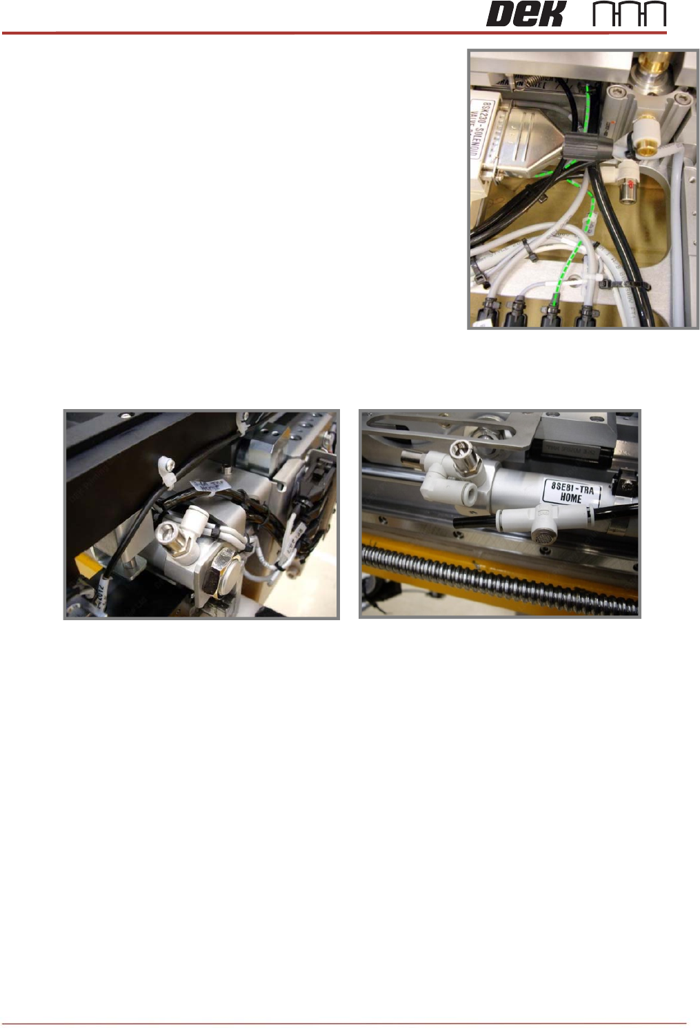
89. Connect the loom marked 8PL224 to the break out
socket plate on the rear of the MEK base.
90. Ensure that the cable is free to move up and down with
the rail cap, any excess can be allowed to loop into the
table casting round the pneumatic pipe.
91. Re-fit the pneumatic pipes to both ends of the LH TRA Sine Cylinder.