TRS Advanced WB Intel Issue 02.pdf - 第30页
TRS Advanced Maintenance 30 Issue 2, Nov 14 Objective 13: Remove and re-fit rail cap assembly The Rail Cap is located across both the Front and Rear Centre Rail sections and houses the linear bearings which guide the Act…
Issue 2, Nov 14
TRS Advanced Maintenance
29
8. Ensure 2 setting blocks move freely up and down but not to left or right.
9. Tighten all active surround screws and torque up to 1.8Nm.
NOTE
Do not drive the rising table to vision height when two setting blocks are fitted.
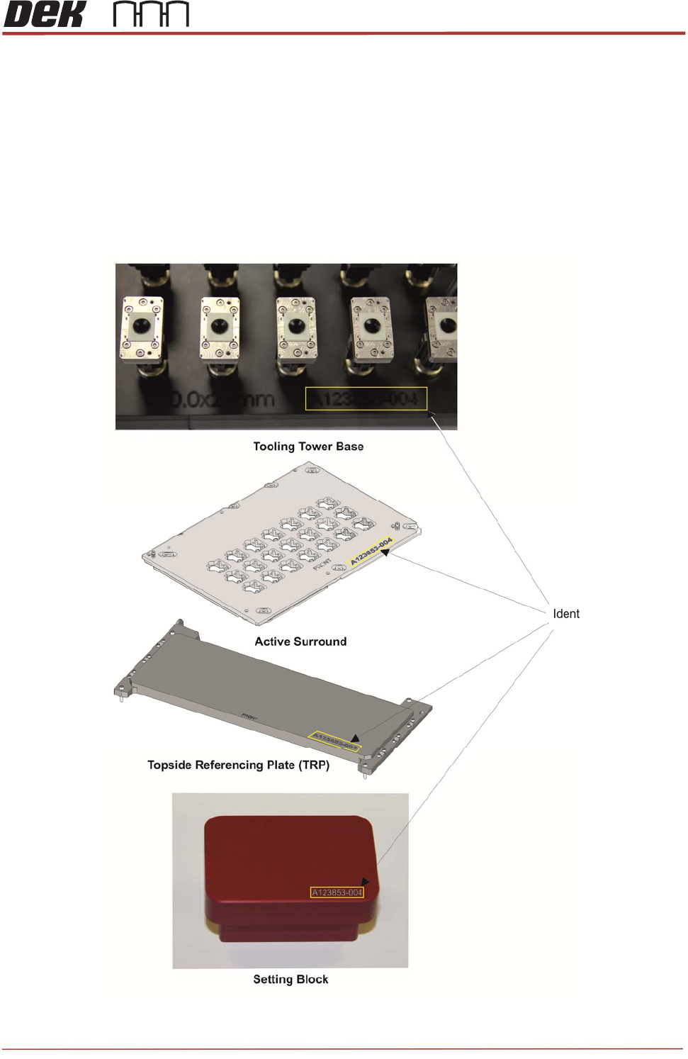
The system tooling has a unique identifier stamped into each unit. Operators and
maintainers should check the identification of tooling before use to ensure they all
match.
TRS Advanced Maintenance
30
Issue 2, Nov 14
Objective 13: Remove and re-fit rail cap assembly
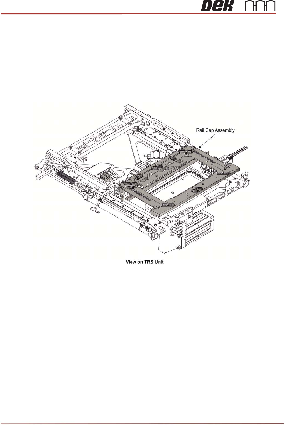
The Rail Cap is located across both the Front and Rear Centre Rail sections and houses the
linear bearings which guide the Active Surround movement. The rear section is mounted on
linear bearings to allow for the rail width to be adjusted, and also contains a snugger to clamp
the carrier in place during substrate lift and printing. There is a tooling sensor on the left hand
side to detect when the Active Surround plate is fitted, and a Rail at Tooling vane mounted on
the rear of the assembly.
Issue 2, Nov 14
TRS Advanced Maintenance
31
Removing Rail Cap from the Printer
1. Drive the rising table to print height.
2. Drive print carriage to rear of the machine.
3. Drive rails to minimum width.
4. Turn the power OFF.
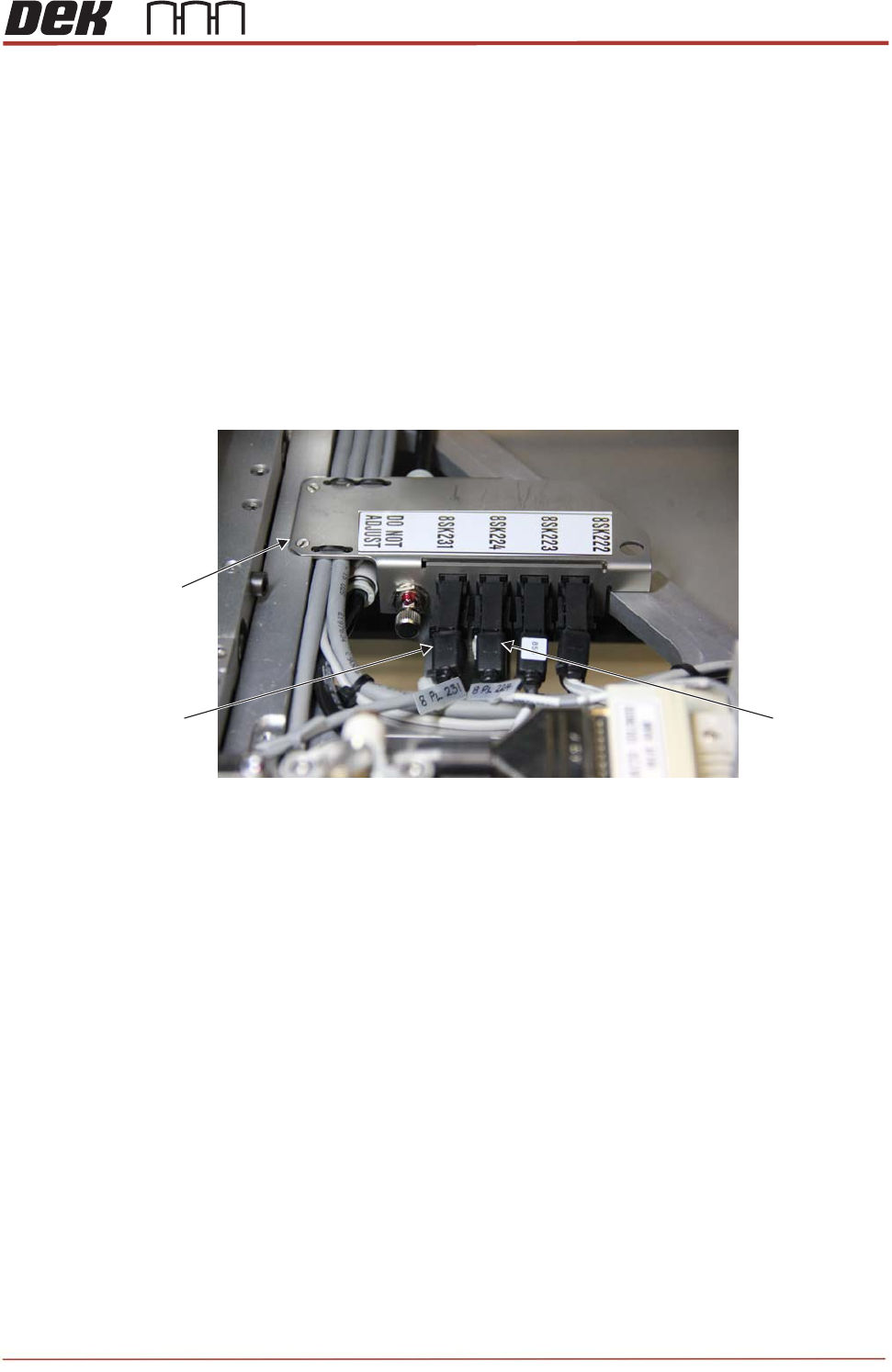
5. Locate looms 215208 and 215210 connected between the rail cap and the interface cover.
Disconnect connectors 8PL231 and 8PL224 from the interface cover. Remove all cable
ties and note the routing of the looms.
6. Disconnect rail cap snugger pipes from Y fitting (behind the rear rail).
8PL231 8PL224
Interface Cover