M3plus_OperationManual_e.pdf - 第30页
1 P art names and functions 1 - 9 5. Conveyor unit The conveyor unit used to clamp a PCB in mounting position consists of the following parts. PCB 2 3 1 4 Con vey or units 23130-5E-20 1 Main stopper When a PCB is carried…
1
Part names and functions
1-8
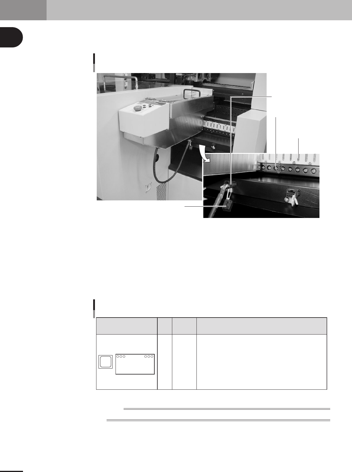
4. Feeder plate section
The standard machine has a compact feeder plate with 16 feeder set positions for installing tape
feeders and stick feeders. Under the feeder plate, there are connectors for signal exchange between
the mounter and feeders, as well as power supply connectors and air connectors for driving optional
units.
Feeder drive air outlet
Signal contact
(8-pin contact)
Connector for TSF1
Shorting connector for TSF1
Feeder plate
23117-5E-20
Signal connector
This connector is used to exchange signals between the mounter and feeders.
Feeder drive air inlet
Supplies the drive air to the feeders.
Connector for TSF1
This connector is used to supply power and signals to the TSF1 (tray shuttle feeder). When this
connector is not used, always attach the shorting connector to it.
Accessible
feeder set No.
Configuration Head
Attachable feeders
1
16
Feeder plate configuration
1
2
3
4
1 to 13
1 to 14
1 to 15
1 to 16
Tape feeders 8mm : Occupies a width of 1 feeder set position
12, 16mm : Occupies a width of 2 feeder set positions
24, 32mm : Occupies a width of 3 feeder set positions
Stick feeders
Occupies a width of 2 or 3 feeder positions
TSF1 Up to 2 units
(One unit occupies a width of 7 feeder set
positions.)
16 in-line feeder set points
(20mm pitch)
23118-5E-20
n
NOTE
Tape feeders with a 15-inch reel and TSF1 can only be used with machines designed for large type tape feeders.
1
Part names and functions
1 -9
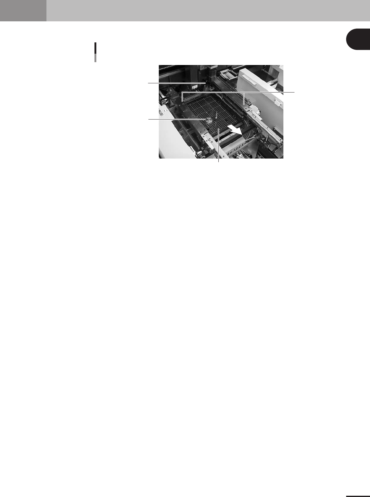
5. Conveyor unit
The conveyor unit used to clamp a PCB in mounting position consists of the following parts.
PCB
2
3
1
4
Conveyor units
23130-5E-20
1 Main stopper
When a PCB is carried in on the conveyor, the main stopper halts travel of the PCB in the component
mounting position.
2 Push-up plate
The push-up plate moves up and down by the air cylinder to support the PCB from the bottom, with
push-up pins attached on the plate.
3 Push-up pins
These pins are arranged on the push-up plate and secure the PCB by pushing it up from the bottom.
4 PCB clamp (PCB clamp unit)
This unit moves up with the push-up plate to clamp the PCB by pushing its edges up.
1
Part names and functions
1-10
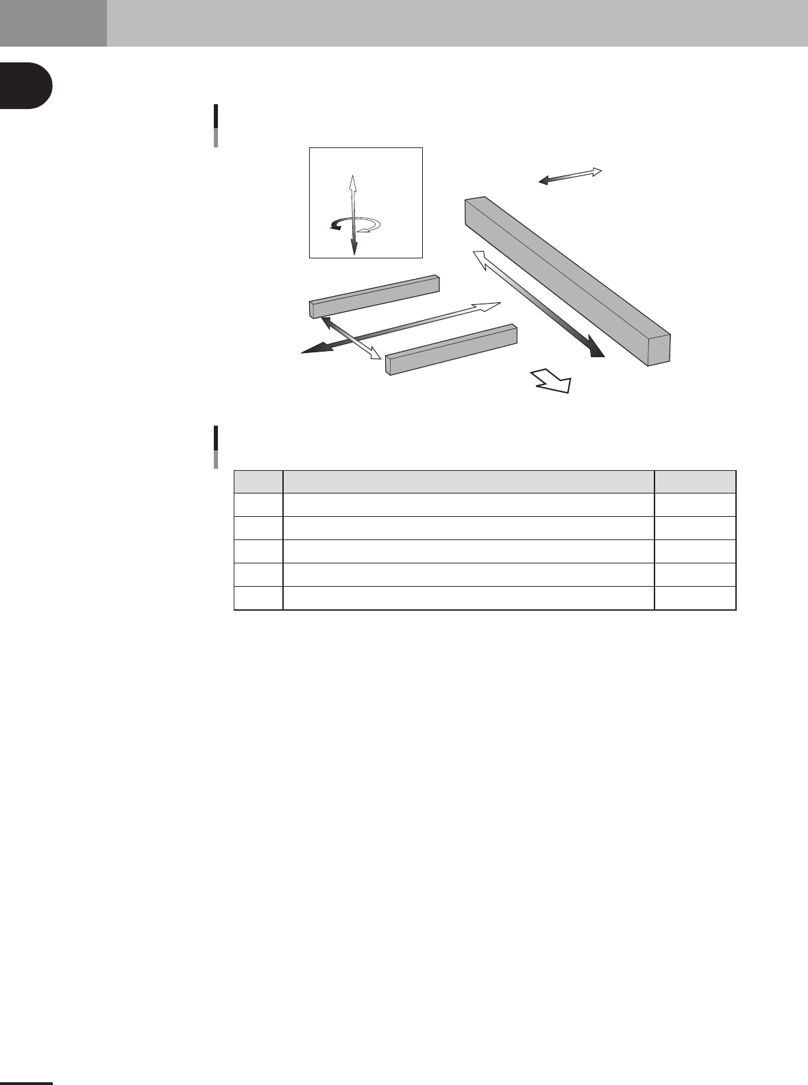
6. Axis configuration
The machine axis configuration and operation are shown in the drawing and table below.
MMM Head
X axis
Y axis
W axis
Z1 to Z4 axis
R axis
Plus
Minus
Front of the machine
Axis configuration and plus/minus directions
23119-5E-20
X
Y
Z1 to Z4
R
W
Axis Function
Function of each axis
Moves the conveyor (W-axis) in the X-axis direction.
Moves the head in the direction perpendicular to the PCB transfer direction on the conveyor.
Controls the height of the head assembly each head.
Rotates the nozzle shafts of the head assembly.
Adjusts the conveyor width.
Remarks
25108-5E-20