M3plus_OperationManual_e.pdf - 第48页
2 - 15 2 Basic oper ation 3. Starting and stopping the machine 3.4.2 Push-up pins The push-up pins are attached on the push-up plate by a magnet and used to correct downward warping of the PCB. Support pin Pushup pin Mag…
2 -14
2
Basic operation
3. Starting and stopping the machine
3.4.1 Conveyor width
First adjust the conveyor width to match the PCB width to be produced.
1
Select the PCB data.
See the description of "2.2 Selecting the PCB data" in chapter 3.
2
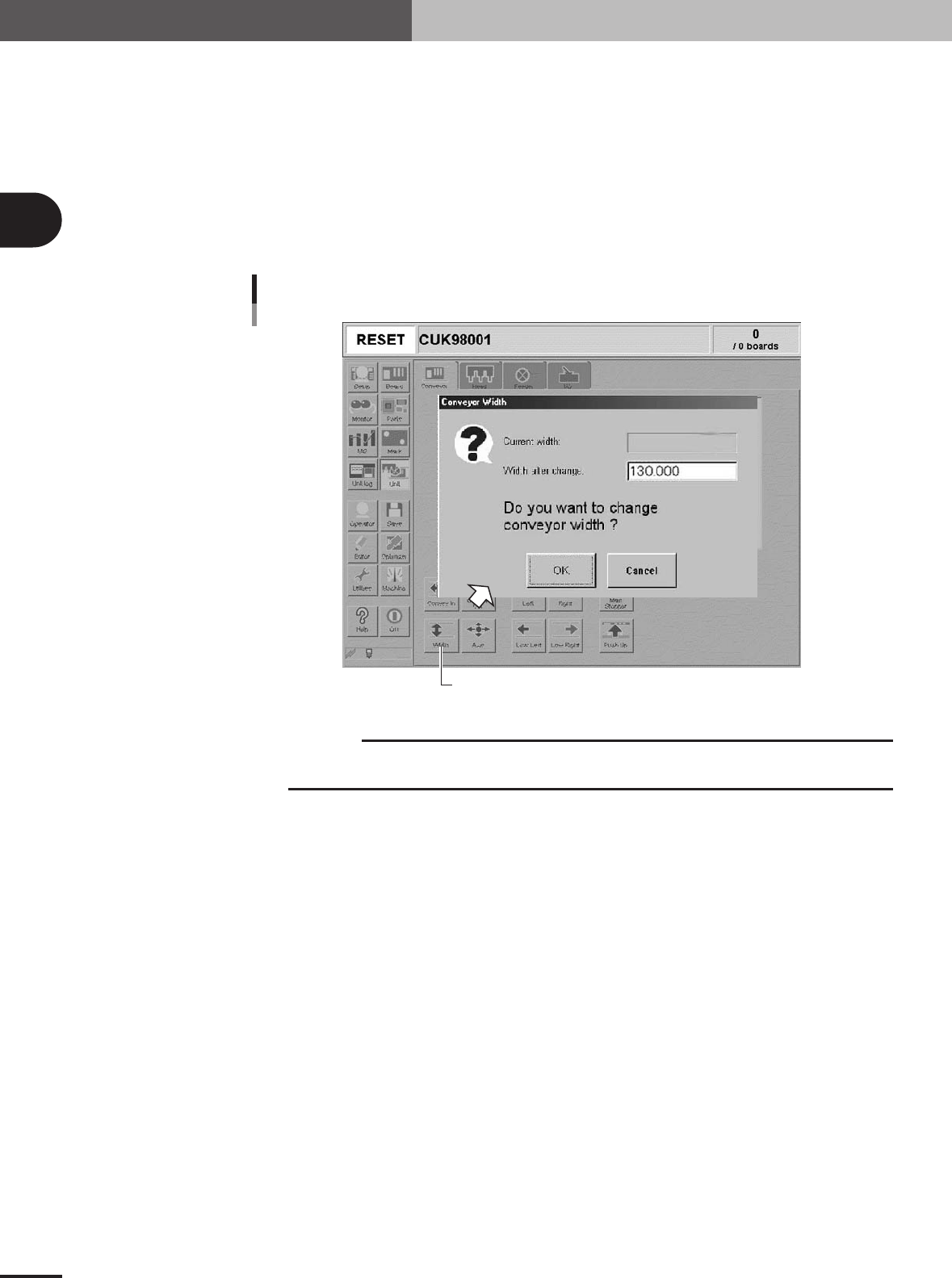
Open the [Unit]-[Conveyor] tab screen.
3
Press the [Width] button.
The Conveyor Width dialog box appears. Check the conveyor width and press the
[OK] button. The conveyor rail automatically changes to the specified width.
[Width] button
Conveyor Width dialog box
27311-5E-20
c
CAUTION
When adjusting the conveyor rail width, make sure that the conveyor rails do not make contact
with push-up pins attached on the push-up plate.
2 -15
2
Basic operation
3. Starting and stopping the machine
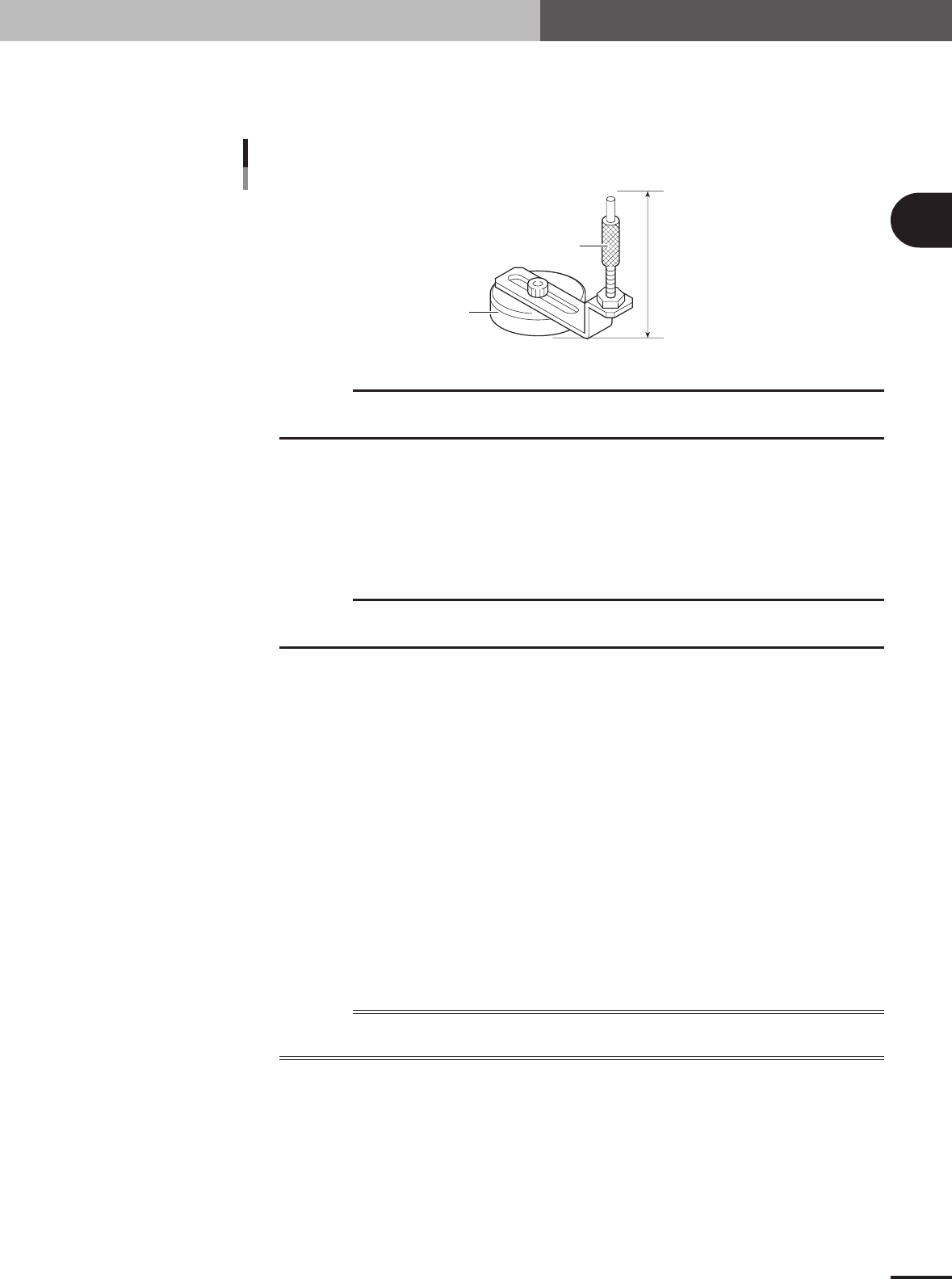
3.4.2 Push-up pins
The push-up pins are attached on the push-up plate by a magnet and used to correct
downward warping of the PCB.
Support pin
Pushup pin
Magnet stand
60mm
23305-5E-20
c
CAUTION
The push-up pin height from the bottom of the magnet to the top of the pin shaft is set to 60mm.
Do not change this height.
1
Press the emergency stop button.
When the machine is in emergency stop, proceed to the next step.
2
Place the push-up pins in the correct positions on the push-up plate.
Considering the shape and size of the PCB, place the push-up pins on the push-up
plate so that they uniformly support the PCB, including the edge of the PCB.
c
CAUTION
Set the push-up pins in positions where they will not interfere with the conveyor rails and other
parts when the push-up plate is raised.
3
Set a PCB on the conveyor.
Press the [Main Stopper] button on the Unit screen to raise the main stopper. Then set
a PCB on the conveyor and place it against the main stopper.
4
Cancel emergency stop.
Release the emergency stop button by turning it clockwise and press the [READY]
button on the operation panel.
5
Raise the push-up plate.
Check safety and press the [Push Up] button to raise the push-up plate. The push-up
plate moves up.
6
Check that the PCB is uniformly clamped on the conveyor.
After pressing the emergency stop button, lightly tap on the PCB and also check for
warping of the PCB from the side. If the PCB is supported evenly with no warping, the
adjustment is okay.
At this point, if the tips of the push-up pins do not reach the bottom of the PCB or the
pins are pushing the PCB up too much, the push-up plate height should be adjusted.
Reference
It may be convenient to mark the positions of the push-up pins on the plate (with a label, magic marker, etc.) for
each PCB type.
e
2
Basic operation
2-16
4. Starting and finishing production
This section describes how to select the PCB data which is already registered and perform component
mounting.
4.1 Starting production
1
Select the PCB data.
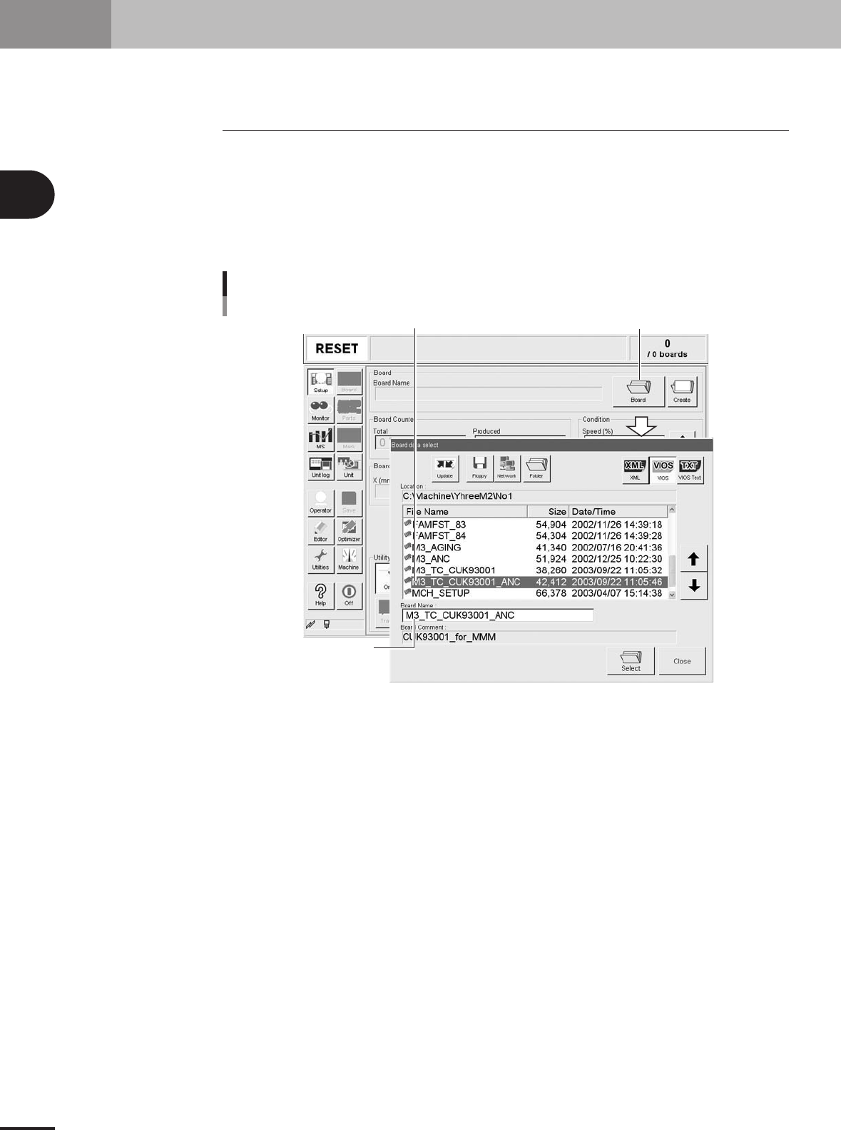
1.When the PCB data is not yet selected, press the [Board] button on the Setup
screen.
A list of registered PCB data appears.
2.Line up the cursor with the PCB data to be produced and press the [Select] button.
The machine loads the selected PCB data.
Press [Board] button.
Selecting the PCB
Select PCB from list.
Selected PCB is displayed.
27303-5E-20