M3plus_OperationManual_e.pdf - 第36页
2 Basic oper ation 2 - 3 2. Operation monitor and buttons The basic configuration and operation methods of the software screens are explained in this section. Please read through this section before operating the machine…

2 -2
2
Basic operation
1.2 Clearing an error
If an error occurs a buzzer sounds and a yellow warning screen appears. To clear the
error, use the following steps.
1
Turn off the buzzer.
Press the [ERROR CLEAR] button on the operation panel or the [BUZZER OFF] button
on the error screen to turn off the buzzer.
2
Check the cause of the error.
Possible causes are displayed on the lower part in the error screen, so check or make
a note of the description.
3
Clear the error screen.
Press the [ERROR CLEAR] button on the operation panel again or the [ERROR CLEAR]
button on the error screen to clear the error screen.
4
Check the signal light and screen display.
Check that the yellow lamp of the signal light is off and the error message on the
upper left of the status area on the operation screen is now off.
1. Before operation
2
Basic operation
2 -3
2. Operation monitor and buttons
The basic configuration and operation methods of the software screens are explained in this section.
Please read through this section before operating the machine.
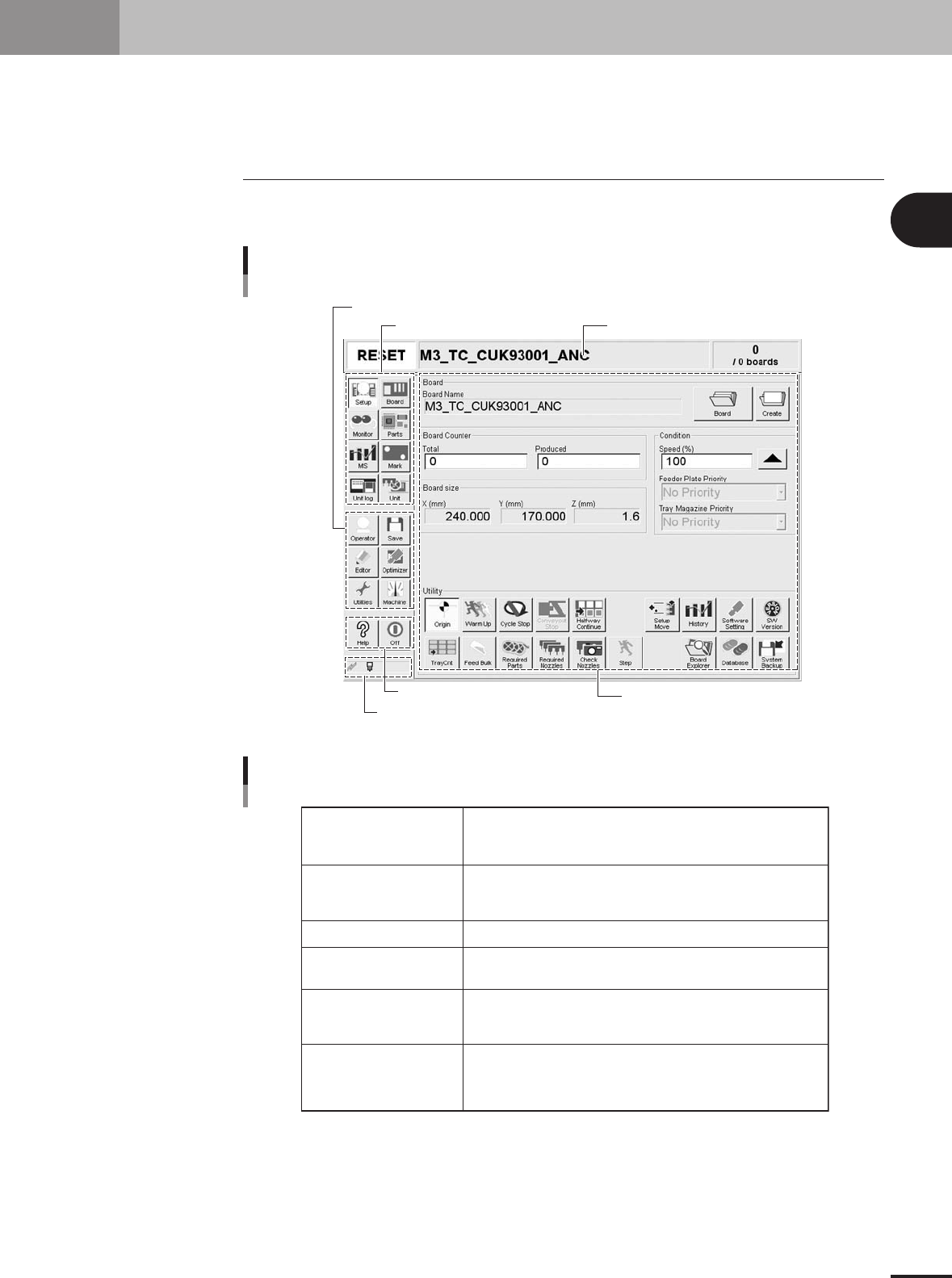
2.1 Basic configuration of operation screen
The operation screen can be divided into the "Status area", "Main menu button area" and
"Submenu button and parameter area" as shown below.
Main menu button area 1
Main menu button area 3
Main menu button area 2
Status area
Submenu button and
parameter area
Indicator area
Operation screen basic elements
Setup screen
27201-5E-20
Status area
Main menu button area 1
Main menu button area 2
Main menu button area 3
Submenu button and
parameter area
Indicator area
Displays the current machine status on the left end, the selected
PCB name in the middle and the number of PCBs that have been produced
on the right end.
Shows the main menu buttons used to operate the machine.
The submenu button and parameter area will change according to the selected
main menu button.
Shows the menu buttons used to call up auxiliary functions of the machine.
Shows the [Help] button to call up the help screen and also the [Off] button
to quit the software.
Displays the submenu buttons and parameters for machine operation and
data setting.
This area will change according to the selected main menu button.
[MSP] icon: Appears in color when the MSP (option) is connected to the
machine.
[Communication] icon: Appears in color when the machine is connected to
an external unit through the RS-232C.
Area on screen
25201-5E-20
2 -4
2
Basic operation
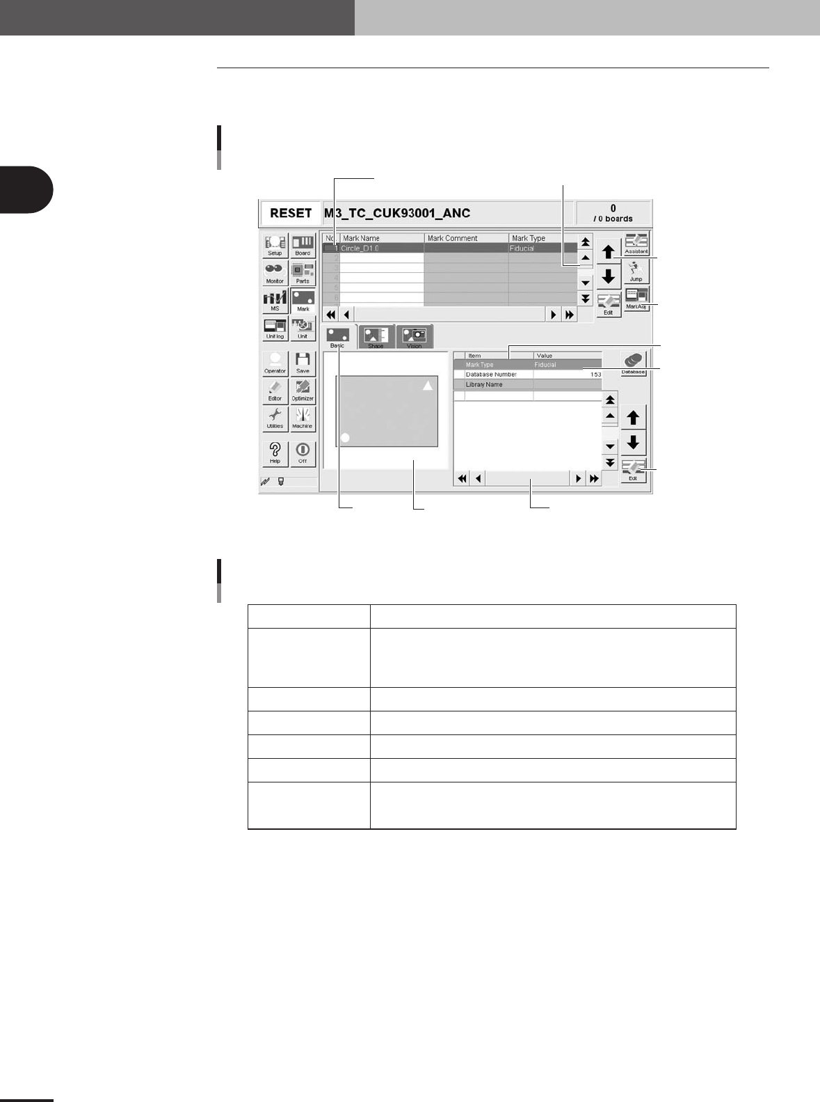
2.2 Various buttons and parameter input boxes
Various types of buttons, selection tabs and parameter input boxes are used on the
operation screen.
Line up/down
button
Ver tical scroll bar & button
Operation screen basic elements
Setup screen
Operation
button
Edit button
Horizontal scroll bar & button
Assistant
screen
Selection
tab
Parameter
list
Parameter
input box
Data No. list
27202-5E-20
Buttons and basic elements on operation screen
Selection tab
Parameter input box
Scroll bar and button
Cursor up/down button
Operation button
Edit button
Assistance screen
Select this tab to switch the parameter input screen.
Select, enter or edit parameters here. When the keyboard is used, double-click on
a parameter input box to enter or edit the data.
When a touch screen (option) is used, press the [Edit] button on the lower right of
the parameter list. The edit box then pops up for data input and editing.
Use the scroll bars or arrow buttons to see hidden items in the parameter list.
Use these buttons to move the cursor up or down through the parameter list.
Press these buttons to open the next operation screen or dialog box.
Press this button to open the edit dialog box for the selected parameter item.
Shows an illustration or information useful for parameter input or editing.
Alphabet characters shown in the parameter list and in the illustration on
this screen correspond to each other.
25202-5E-20
2. Operation monitor and buttons