M3plus_OperationManual_e.pdf - 第92页
3 - 27 4. Creating the component information 3 Creating the PCB data E: Feeder Type Select the specific feeder type to be used for component supply. Selectable items differ depending on the Package parameter setting. Ref…
3 -26
3
Creating the PCB data
4. Creating the component information
• Ignore
This does not perform image processing.
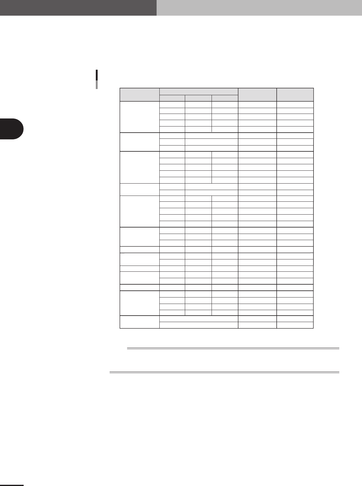
C: Required Nozzle
Select the optimum nozzle that matches the component size from among the nozzle types for chip
components. When the parameter values are copied from the database, use the default setting.
Component
Size (mm)
Box type chip
Cylindrical chip
(Melf type
component)
Ceramic
capacitor
Tantalum
electrolytic
capacitor
Aluminum
electrolytic
capacitor
SOP
PLCC, QFP, BGA
Chip inductor
Semi-variable resistor
Mini-mold
transistor
Power transistor
Chip film capacitor
Melf type
capacitor
LWT
Nozzle type
Required
Nozzle Setting
Typical component and suitable nozzles
0.60
1.00
1.60
2.00
3.20
2.00
3.45
5.90
1.50
2.00
3.20
3.20 to 4.50
5.60
3.40
5.90
2.90
3.80
4.70
6.00
7.30
4.30
6.60
10.00
7.30
3.20
4.50
4.50
2.90
4.00
4.60
5.00
7.60
10.10
12.60
0.30
0.50
0.80
1.25
1.60
0.80
1.25
1.60
2.50 to 3.20
5.00
1.60
2.90
2.60
3.20
4.30
4.30
6.60
10.00
5.30
2.50
3.20
3.80
1.50
3.00
2.60
4.50
4.50
4.50
5.70
0.25
0.50
0.50
0.50
0.60
0.80
1.25
1.25
1.50 to 1.90
1.90
1.60
1.60
2.10
2.50
2.80
5.70
5.70
10.50
3.25
2.00
3.20
2.40
1.10
1.80
1.60
1.50
1.50
1.50
1.50
Type 81A
Type 82A
Type 82A
Type 84A
Type 82A
Type 82A
Type 82A
Type 86
Type 82A
Type 82A
Type 82A
Type 83A
Type 83A
Type 82A
Type 8SA
Type 82A
Type 83A
Type 83A
Type 83A
Type 83A
Type 83A
Type 83A
Type 84A
Type 83A
Type 83A
Type 83A
Type 83A
Type 83A
Type 83A
Type 83A
Type 83A
Type 83A
Type 84A
Type 84A
Type 83A
Type 84A
For0603CHIP
For1005CHIP
For1608CHIP
For2125CHIP
For3216CHIP
ForMELF S
ForMELF M
ForMELF L
For1608CHIP
For2125CHIP
For3216CHIP
For4532CHIP
For5650CHIP
ForMELF M
ForMELF L
For3216CHIP
For4532CHIP
For5650CHIP
For7343CHIP
For7343CHIP
ForALC S
ForALC M
ForQFP 20mm
For7343CHIP
For4532CHIP
For4532CHIP
ForVR L
For3216CHIP
For4532CHIP
For5650CHIP
ForSOP 10mm
ForSOP 10mm
ForSOP 20mm
ForSOP 20mm
ForSOP 10mm
ForQFP 20mm
5x5 to 10x10mm
10x10 to 31x31mm
(up to 24x24 for Heads 1 and 4 )
1.25
1.35
2.20
1.50
2.20
25001-5E-20
n
NOTE
If using a custom nozzle designed for the connector, select the corresponding type from among "Sp. Nozzles A to
F". In other cases, select the optimum nozzle that matches the connector size from among the nozzle types for
SOP components.
D: Package
Select the type of component feed.
"Tape"
Select this setting when using a tape feeder which supplies components on paper tape, embossed
tape or adhesive tape.
"Stick"
Select this setting when using a stick feeder such as a stack stick feeder or high-speed stick feeder.
"Bulk"
Select this setting when using a bulk cassette feeder.
"Tray"
Select this setting when supplying components from Tray Shuttle Feeder (TSF1).
3 -27
4. Creating the component information
3
Creating the PCB data
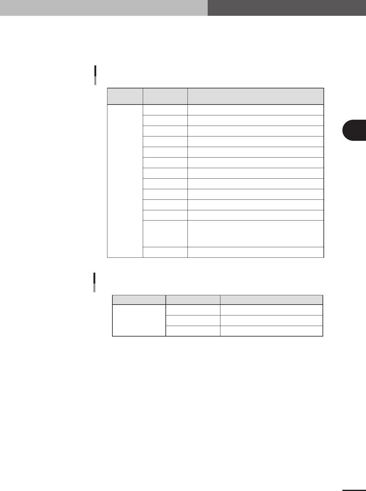
E: Feeder Type
Select the specific feeder type to be used for component supply. Selectable items differ depending
on the Package parameter setting. Refer to the table below to make a selection. When the Package
parameter is set to "Stick" or "Tray", see "4.7 Setting the stick feeder component data" or "4.8
Setting the tray component data" in this chapter.
Comp.
Package setting
Tape feeder or bulk cassette feeder type Feeder Type setting
Feeder Type settings
when "Package" is set to "Tape"
Tape
8mm tape feeder (except for 1005, 0603 chip)
8mm tape feeder (for 1005 chip)
8mm tape feeder (for 1005, 0603 chip)
12mm tape feeder (standard pitch)
12mm tape feeder (long pitch)
16mm tape feeder
24mm tape feeder
32mm air-driven feeder with sticky tape
32mm embossed air-driven feeder
44mm embossed air-driven feeder
56mm embossed air-driven feeder
Select these settings when using a tape feeder other than the above.
Note that you must make necessary settings on the <3/1/A5 FEEDER
SPEC. INF> screen. For the setting procedure, refer to the mounter
service manual.
8mmTape
8mm1005cmp
8mm0603cmp
12mmEmboss
12mmLongPitch
16mmEmboss
24mmEmboss
32mmSticky
32mmEmboss
44mmEmboss
56mmEmboss
Tape-A to D
Spear1 to 10
25403-5E-20
Comp. Package setting Tray feeder typeFeeder Type setting
Feeder Type setting
when "Package" is set to "Tray"
Tray
Tray shuttle feeder (TSF1)
Not available
Not available
Fix. TF
Ext. TC
Auto TC
25404-5E-20
3 -28
3
Creating the PCB data
4. Creating the component information
G: Dump Way
This specifies the location where a component will be dumped if an error such as recognition error
has occurred. Set to "Dump POS" for chip components and small components.
H: Retry Times
This determines how many times the machine will retry the same operation if an error such as a
recognition error has occurred. The number of retries can be set from "NO RETRY" to "14". When
this retry setting is greater than the machine data retry setting, the machine data has priority.
I: Conveyor X Speed
The conveyor X-axis moving speed can be selected. If components tend to move or slide (such as
tall components) just after mounted on the PCB due to the X-axis movement, set this parameter to
a lower speed to prevent it. Select the optimum speed from among "FAST", "MEDIUM", "SLOW"
and "VERY SLOW".
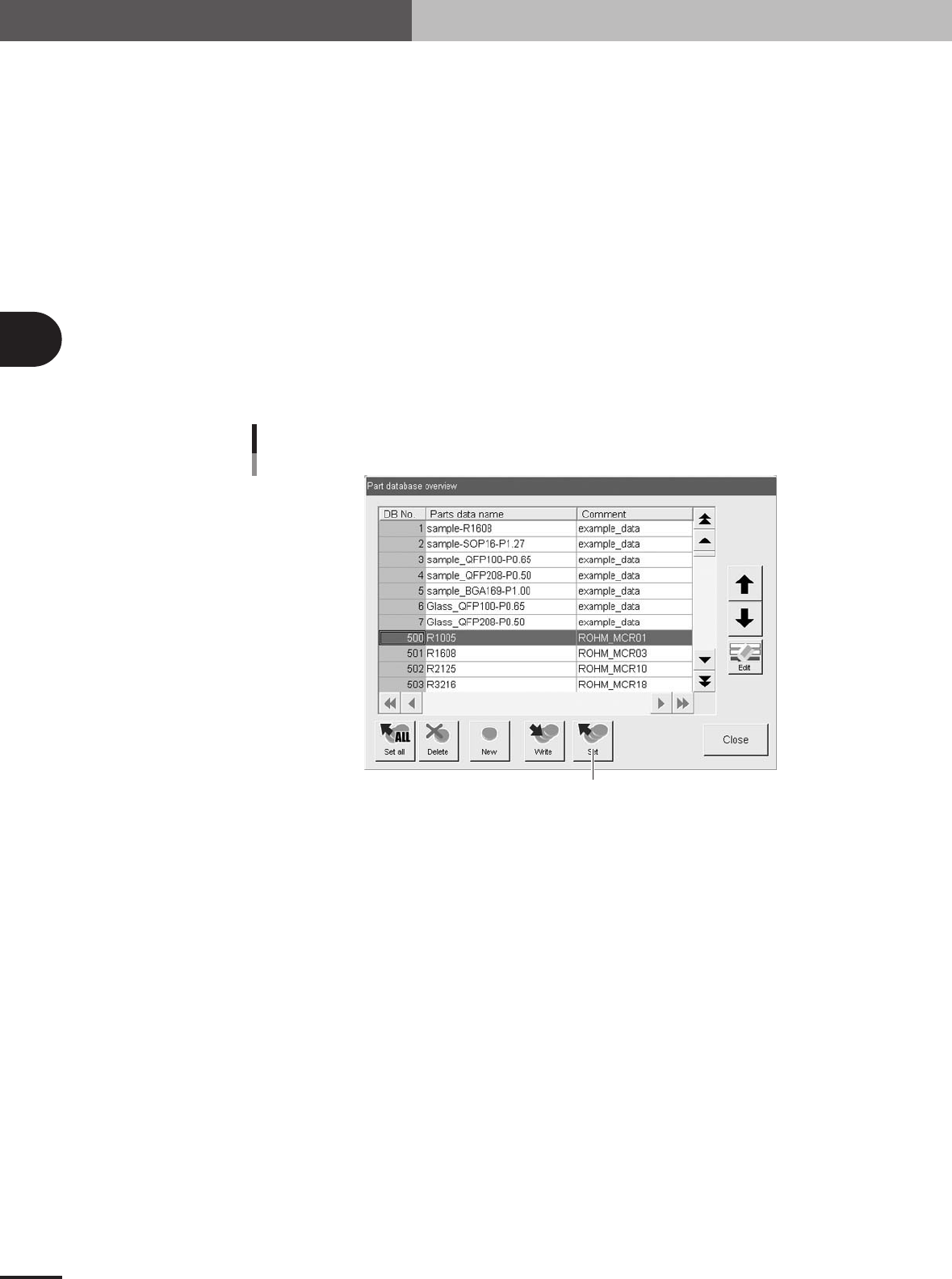
J: Database number
Shows the database number when the parameter values were copied from the database.
When you want to copy the parameter values from the database, press the [Database] button to
open the database list. Then select the copy source data and press the [Set] button to make a copy.
Press this button.
Database set
27413-5E-20
K: Library Name
The name of the component data library is displayed. This data library can be managed in the
machine or on a PC connected to LAN. (When using the data library, see "3. Creating XML
library" in chapter 6.)