IPC-7526-2007 模板和误印板清洗指南.pdf - 第8页
www.bzfxw.com Figure 1-2 Solder Paste Buildup on Walls of Stencil Apertures Figure 1-3 Solder Paste Buildup on Walls of Stencil Apertures (Figur es 1-2, 3) Solder balls attach to the walls of the stencil aperture over ti…
www.bzfxw.com
Stencil and Misprinted Board Cleaning Handbook
1 INTRODUCTION
1.1 Scope
This Handbook addresses the removal of sol-
der paste and uncured/unreacted SMT adhesives from sten-
cils, misprinted printed circuit boards (PCBs) and applica-
tion tools connected to the soldering paste application
processes.
1.2 Purpose The purpose of this handbook is to provide
a basic understanding of stencil/misprint cleaning pro-
cesses. The handbook serves as a guide to users or prospec-
tive users of stencil/misprint cleaning technology.
1.3 Overview Cleaning of stencils and misprinted PCBs
has taken an increasingly important role in surface mount
technology. Fine and ultra-fine pitch lands, together with
other advanced packages, place new demands on stencil
cleaning. Paste volume is a critical issue for fine, ultra-fine,
chip-scale, BGA and flip-chip components. Insufficient sol-
der due to clogging of stencil apertures is a primary cause
of defects. This results in poor paste printing and therefore;
clean stencils are important in delivering the proper amount
of paste. Process engineers estimate that approximately
70% of surface mount technology defects are due to solder
paste printing problems.
Cleaning agents must be effective, safe for workers, and
safe for the environment. Isopropyl alcohol (IPA), com-
monly used for cleaning, poses both environmental (VOC)
and safety (i.e., fire hazard) concerns. Today, a much wider
array of cleaning agents exists for stencil cleaning.
The residue encountered on stencils is generally nonre-
flowed solder paste. After hours of use, the solder paste
may partially dry. This increases the difficulty of cleaning.
In addition, there is also a need to remove uncured SMT
adhesives used for bottom side mounting of surface mount
devices. These issues afford the same cleaning problems
for misprinted PCBs.
Section 2 provides a partial listing of documents and refer-
ences that may need to be considered in the stencil clean-
ing process.
Appendix A provides definitions for terms used in this
handbook.
1.4 Problem Statement Proper stencil cleaning should
remove all solder particles and flux vehicle (organics) from
stencil apertures without damaging the stencil, bonding
adhesives, and elastomer frame. Solder paste residue on a
stencil can result in transferring paste from the bottom of
the stencil onto the next board printed. The residue can also
interfere with good ‘‘gasketing’’ of the stencil to the board
being printed. Any of these conditions can cause misprints,
solder paste where it should not be, or missing solder paste
from where it should be, resulting in shorts, solderballs, or
lack of sufficient solder paste when the PCA is reflowed.
1.5 Common Production Problems Printing or dispens-
ing of solder paste is a crucial step in production of SMT
PCAs. The stencils used must be clean and free of solder
paste residue to avoid misprinting/misapplying solder paste
deposits to PCAs. Additionally, the wetness and thixotropic
property of the paste being applied, flatness of the PCA,
the positioning of the stencil with respect to the PCA lands,
the squeegee pressure, stencil aperture opening in relation
to the PCA land dimensions, type of stencil technology, etc.
can all result in solder paste being left on the stencil.
For the reasons stated above, the bottom of the stencil
requires inspection, monitoring and wiping throughout the
process. Printers provide various methods to wipe the sten-
cil bottom. For printers that do not provide understencil
wiping, manual methods must be employed.
Failure to implement a process that removes residue from
stencil apertures contributes to board processing problems.
Factors outside the cleaning process may also contribute to
process issues. Figures 1-1 through 1-10 identify issues
that contribute to stencil printing problems.
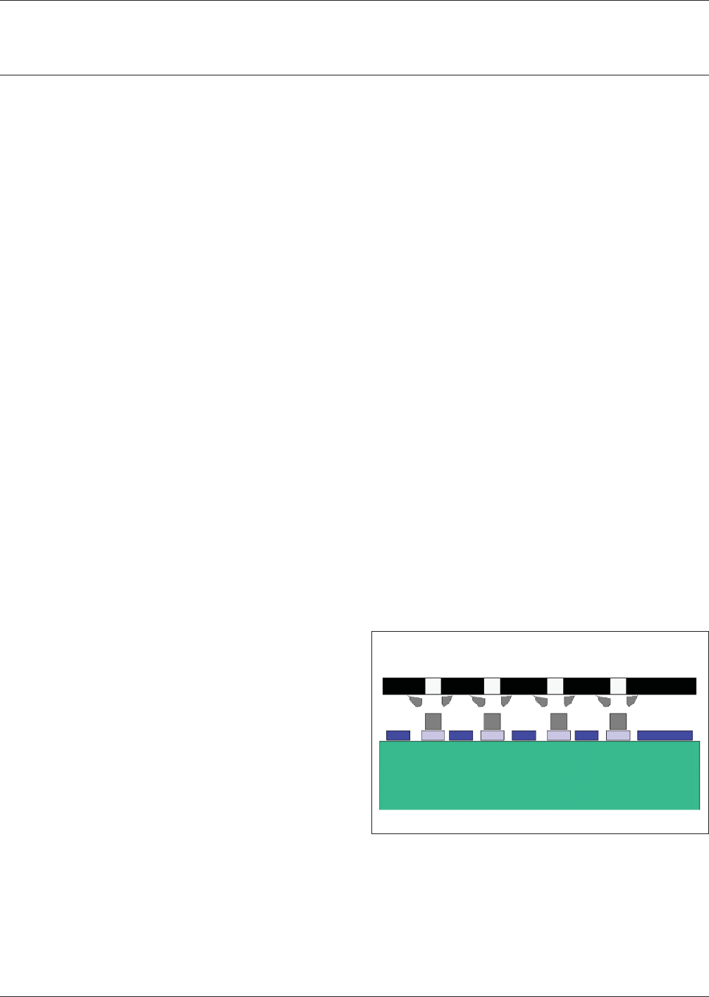
IPC-7526-1-1
Figure 1-1 Cleaning Stencil Bottom
(Figure 1-1) Failure to underwipe or clean the bottom side
of the stencil contributes to inconsistencies in solder paste
deposition.
Cleaning Stencil Bottom
February 2007 IPC-7526
1
www.bzfxw.com
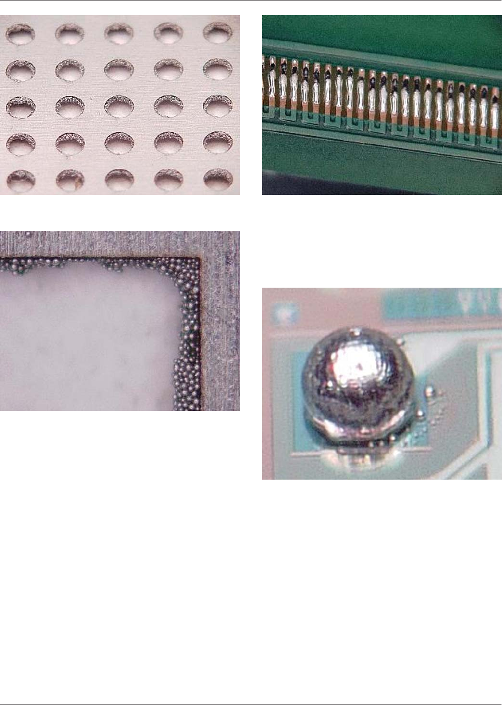
Figure 1-2 Solder Paste Buildup on Walls of Stencil
Apertures
Figure 1-3 Solder Paste Buildup on Walls of Stencil
Apertures
(Figures 1-2, 3) Solder balls attach to the walls of the
stencil aperture over time. Failure to clean this buildup
from the stencil affects the amount of deposited solder
paste and could potentially cause open solder joints, bridg-
ing, and solder ball formation on the subsequent PCA.
Figure 1-4 Open or Insufficient Solder Joints
(Figure 1-4) When solder paste and/or the flux vehicle is
not completely removed from stencil apertures in the clean-
ing operation the dried residue partially or completely
blocks the correct volume of solder paste, resulting in
insufficient or open solder connections.
Figure 1-5 Solder Balls Following Solder Reflow
(Figure 1-5) Water or solvent remaining on circuit boards
or stencils following cleaning may be mixed with the sol-
der paste resulting in satellite solder ball formation in the
solder reflow process. Improper cleaning of solder paste
from miprinted boards can leave large quantities of solder
balls from the solder paste on and around the lands and in
the vias.
IPC-7526 February 2007
2
标准分享网 www.bzfxw.com 免费下载
www.bzfxw.com
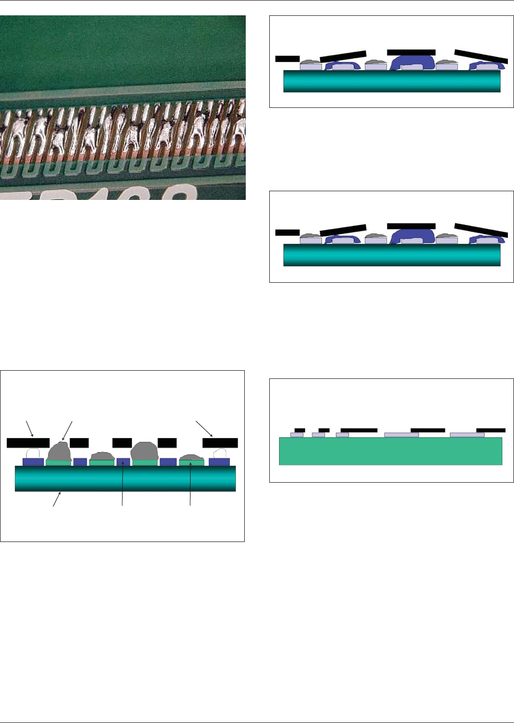
Figure 1-6 Bridging or Poorly Defined Solder Paste
Printing
(Figure 1-6) Damage to the stencil patterns during
removal of excessive solder paste or in a cleaning process
will result in poorly defined joints or bridged parts.
Improper rinsing of stencils can leave surface contaminants
or residual cleaning fluid on the surface of the stencil.
These contaminants promote flux bridging under the sten-
cil during the printing process. The release of the board
from the stencil creates a vacuum as the stencil separates
from the board, sucking the solder paste beneath the sten-
cil, leaving poorly defined prints or bridges.
IPC-7526-1-7
Figure 1-7 Failure to Place the Stencil on a Level Plane
(Figure 1-7) The stencil must sit on a level plane that is flat
with well-identified points and lines. The stencil should
contact the board at the solder mask height. Variations in
hot air solder leveling (HSAL) or excessive legend ink
thickness can lead to poor gasketing, which will allow sol-
der paste to flow beyond the aperture opening on the bot-
tom of the stencil resulting in poor print definition.
Board Coplanarity
Stencil
Solder
Level
Board
Ledgend
Solder
Mask
Copper
Pad
FR4
Composite
Material
IPC-7526-1-8
Figure 1-8 Variations in Solder Mask Thickness
(Figure 1-8) Variations in solder mask thickness contribute
to inconsistencies in solder paste deposition. This condition
is similar to the board coplanarity problem and will lead to
poor definition and increase the need for stencil wiping.
Solder Mask Thickness
IPC-7526-1-9
Figure 1-9 Inconsistent Component Land Width
(Figure 1-9) Component land width must be consistent.
Variations contribute to inconsistencies in solder paste
deposition. If the land is smaller than the aperture, paste
will flow beyond the land and if soldermask is not present,
the possibility of bridging between the lands will increase.
Solder Mask Thickness
IPC-7526-1-9
Figure 1-10 Misaligned Stencil
(Figure 1-10) Poor alignment contributes to inconsisten-
cies in solder paste deposition and increases contamination
of the stencil bottom. This leads to poor definition on sub-
sequent prints and increased frequency of the stencil bot-
tom cleaning to maintain acceptable print quality.
Alignment Accuracy
0.016˝ pitch
0.050˝ pitch
February 2007 IPC-7526
3