X4电路图.pdf - 第126页
2 - 71 Z03_20 X4-0201 01LD3 Z axis, 20- segme nt C&P h ead, gantr y 3, S IPLACE X4 (sh. 2 of 2 ) GND AGND -15V +15V_Servo +5V X4sb C1 C5 AGND End sig nal 03036027 (sb) Axis card A364, gantry 3 SDS60/3Z1 servo amplifi…
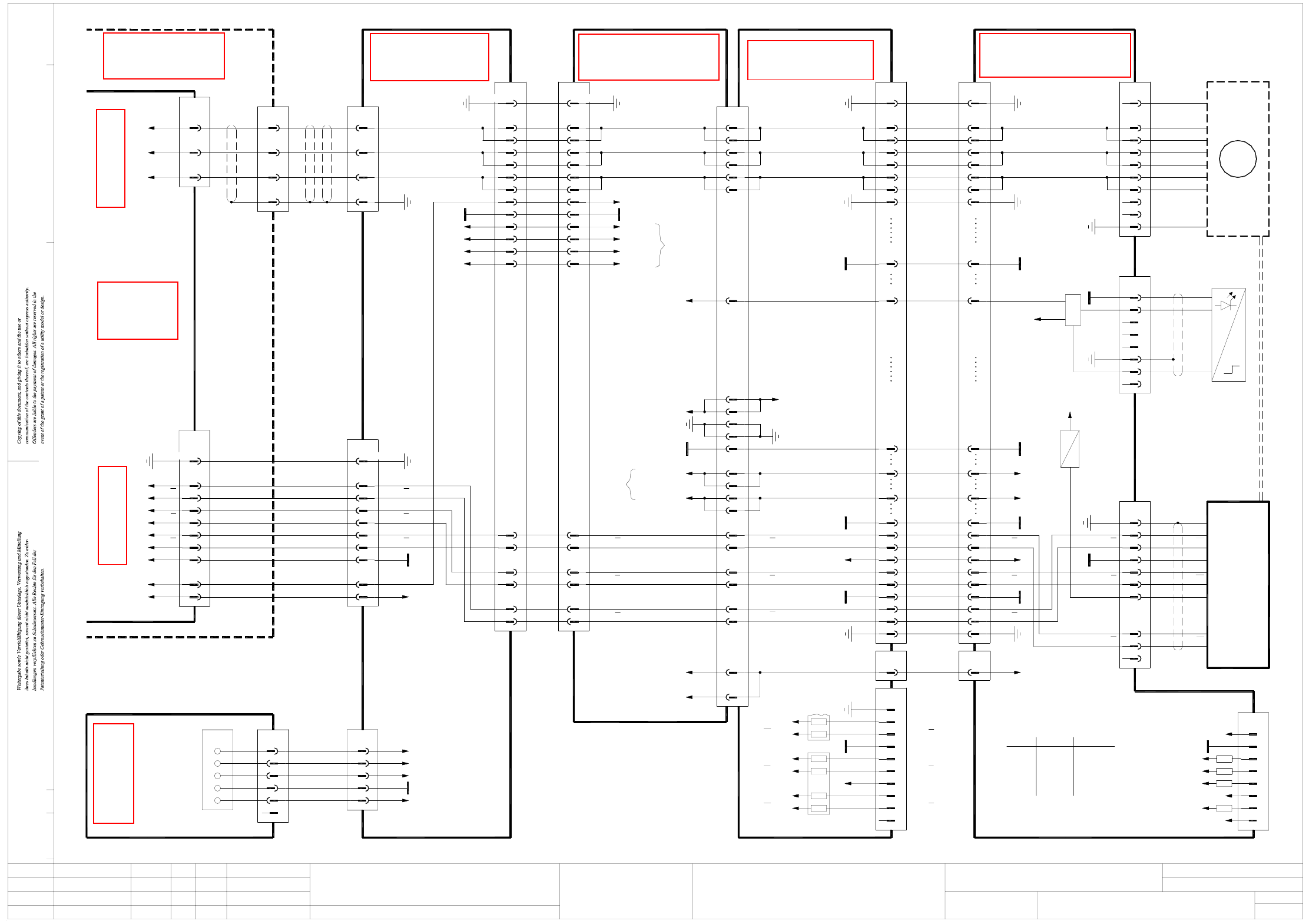
2 - 70
Z03_20X4-020101LD3 Z axis, 20-segment C&P head, gantry 3, SIPLACE X4 (sh. 1 of 2)
72
97
X2:11
18
PGND18
16
13
7
8PE
Z_BOTTOM_X2
16
13 GND
7
8 PE
105
101
99
X22cc/J3
103
Z motor V
Z motor U
C&P20 head adapter
03002870 (cq)
3
5
4
2
1PE
X1cq
03012097-W1
3
5
4
2
1
X1cs
PE
6
03005183
3
Key
LOGIC
15V
+15V
n.u.
n.u.
Key
PE
EMERGG1
6
8
7
5
4
Sensor
Z bottom, C&P20
03007833
n.u.
n.u.
AGND
X17cs
2
1
PE
n.u.
9
10
8
7
03007833
3
5
4
2
X8cs
1
Z drive
3 ~
M
X18:8
X18:14
J3:60
Gantry 1 or 3
03010612 (ca)
Cable carrier interface
Z motor V
Z motor U
2
1
X14ca
Z1/DP1 motor
03038097
Carrier cable 7, 2GO
2
3
5
4
1,8,9,10,34PE
X7ca
Z motor U
Z motor V
3
5
4
2
PE
X7cc
1,8,9,10,34
5V
LOGIC: Z_BOTTOM_X2
green
yellow
yellow
Color
green
green
GND
Track B,
Track B,
Track N,
Track N,
R14
470R
8
4
6
2
J3:58
J3:56
J3:46
J3:44
7
5
3
1
Key
9
10
8
6
7
5
VCC
VCC
Track N
Track N
Track B
Track B
D8
D5
D6
D3
D4
(Z sensor stop)
+15V
GND
GND
GND
50 Track A
Track A
Z_BOTTOM_SENSOR
Track A,
Track A,
X7cc:15
X1cc:18
61
60
48
8
6
J3:50
J3:48
7
5
R13
470R
Track N
Track B
Track B
Track N
58
46
44
56
+15V
-15V
90
89
88
87
38 38 Track A
2
4
3
1PE
X5cq
PE
Track A
Track A
Z tracks
Test plug
11
X2cq
39
40PE
Document st.
Product st.
Function st.
1. Hi
Hi1.
Hi2.
Z03_20X4-020101LD3
10.07.06
10.07.06
10.07.06
11.01.2005
Copyright reserved
SIEMENS AG
Gantry 3
SIPLACE X4
PE
Key
BU
RD
PK
OG
WH
03046225 (qa)
Main distributor
+24V
0V
+5V
+15V
-15V
X1qa
Z sensor stop
Z track A
Z track A
Z track B
Z track B
Z track N
Z track N
Sheet 2
18
+5V 12
11
OPTO_GND 10
19
25
24
21
22
1WH(W1)
n.u.
BN
GN
41
6
5
2
3
2
(W2)
(W2)
(W1)
(W1)
Cable carrier interface
X5qa
Voltage
03009808
03044425-W3
BN
RD
BK
Phase_W BN3
Backplane
Axis unit
03039648 (sq)
X1up /
1,4,7,17,20,23,26
X08_1sq
26-pole
03042047
Axis unit, gantries 2 and 3
Sheet 2
X3uy /
X08_3sq
Phase_V 2
Phase_U 1
03012097-W2
LED
Track A
Z_BOTTOM_X2
11
X2cs
40
39
PE
32
35
36
37
33
34VCC
31
20
28
-15V
32 Track N
Track B
Track B
Track N
35
37
36
GND
34
33
+5V
+15V
31 GND
20
28
-15V
LOGIC: Z_BOTTOM_RESET
LOGIC: Z_BOTTOM_X2
-15V
Z bottom
+15V
Z top
+5V
-15V
+24V_DP
+15V
+5V
7
8
6
4
5
3
03005183
X14cs
Key
Function
Key
Track N
Track N 9
10
8
CAN_RX
GND
1
2
Test plug
2Track A
GND
Track B
Track B
Track A
5
7
6
4
3
PE
+5V_ENCODER
X6cs
1
C&P20
Encoder
C&P20
Z drive
Z_BOTTOM_RESET
C&P20 intermediate distributor
03002942 (cs)
Z motor W
Z motor V
Z motor U
95 Z motor W 6 6
GND
PGND
PE
GND
VCC
134, 140
92
85
91
83
PE
VCC
Z_BOTTOM_RESET
DC/DC converter
X1cc:2
RD
BK
BNBN44
03009814
Actual value
Z1 axis
BK
41 BK
Cable carrier interface
GN
WH
43
X22
42
GN
WH
03009803
Z1 motor
Head interface
03000901 (cc)
Gantry 3
Service connector
Z sensor stop
Service connector
X19:9
X19:11
DC/DC converter
+24V1
GND4
5 +5V
3
2
+15V
-15V
X50ca
Z track N18
Z sensor stop
Z track N
12
11
+5V
10
19
GND
Z track A
Z track A
Z track B
Z track B
25
24
21
22
PE
Z track A2020
21
Z track A21
17
24
23
18
Z track N17
Z track B
Z track B
Z track N
23
24
18
6 Z motor WZ motor W3 6
1,4,7,17,20,23,26
X24ca
4
PE
+15V 25
28+24V
19
15
22
16, 31
7
GND
-15V
+5V
Z sensor stop
+15V25
+24V28
X18:2,4,6
X18:12
GND
-15V
+5V
Z sensor stop
16, 31
19
22
15
7
ModifiedStatus Date
CAD file : Z03_20X4-020101LD3_SH01.DWG
Orig./Repl.f./Repl.byStand.Name
Check.
Mat. no. :
Author Hi
Date
Sh.
Sh.
SIPLACE X-Series
1
2
Z axis, 20-segment Collect&Place head
C&P20
Motor
26-pole
34-pole 34-pole
140-pole
40-pole 40-pole
Key
Key
GN
BU
VT
OG
BN
RD
YE
GY
W
GND
W
U
U
V
V
BK
RD
BK
BN
BN
GY RI
RI
YE
RD
BK
PK
GN
WHGN
WH
T2
+5V
T2
GND
T1
T1
See page 5-41
See page 4-7
See page 5-57
See page 5-28
See page 5-33
See page 5-34
See page 4-9
2 - 71
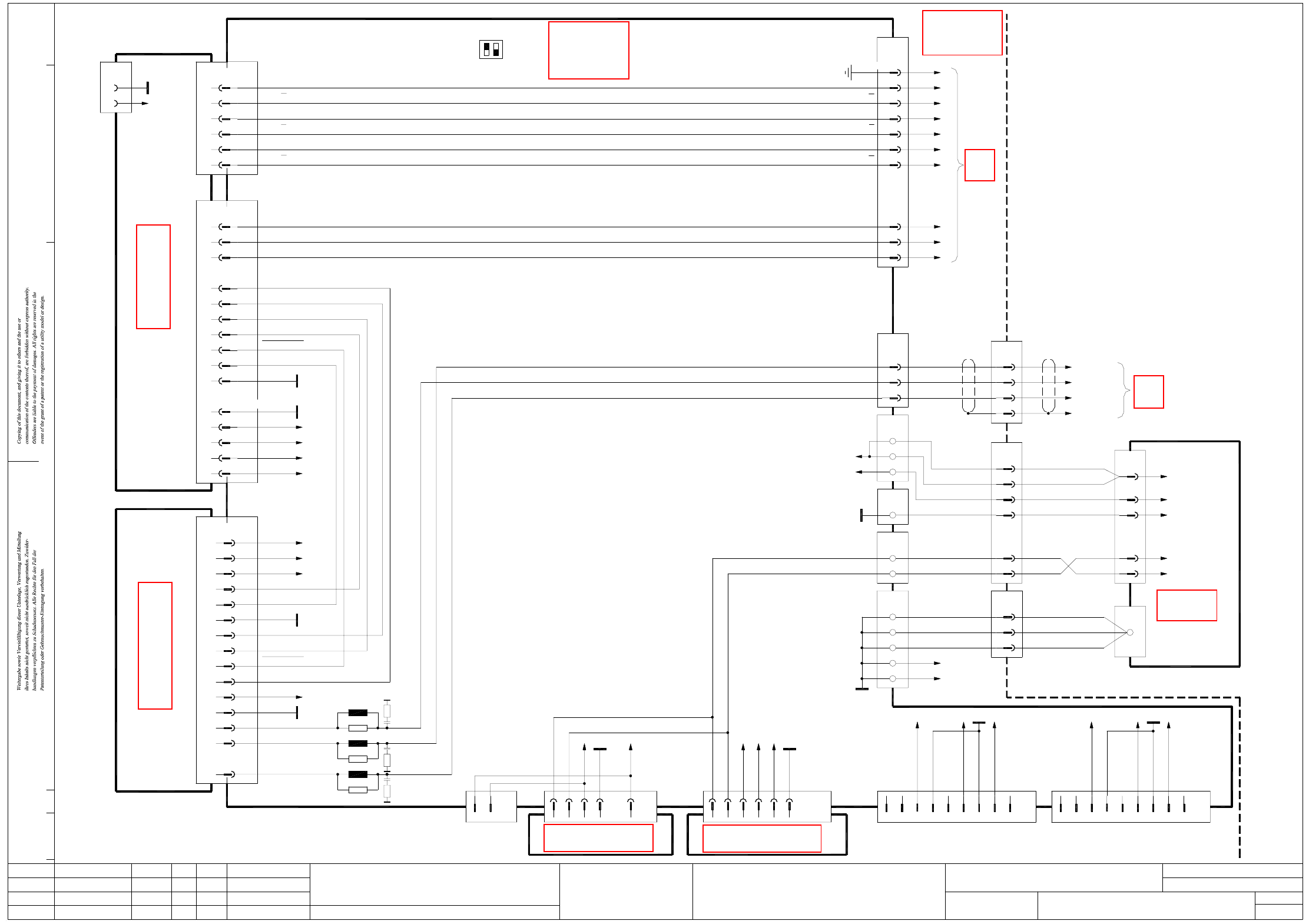
Z03_20X4-020101LD3 Z axis, 20-segment C&P head, gantry 3, SIPLACE X4 (sh. 2 of 2)
GND
AGND
-15V
+15V_Servo
+5V
X4sb
C1
C5
AGND End signal
03036027 (sb)
Axis card A364, gantry 3 SDS60/3Z1 servo amplifier
03002141 (sq)
Track A
Track A
Track B
Track B
Track N
Track N
OPTO_GND
UB_Power_OK
Inom_W
Inom_U
+15V_Servo
-15V_Servo
Servo_Ready
AGND
Inom_W
Inom_U
Servo_Enable
+40V_Z/DP
UB_Power_OK
+150V_Star
Phase_V
Phase_U
Phase_W
Gantry 3
D18
Servo_Enable
Servo_Ready
I²t
PGND
C22; A/C24
C16 I²t
41
42
43
44
X22 03009803
1
2
3
X3uy /
03044425-W3
BK
RD
BN
BK
RD
BN
Phase_U
Phase_V
Phase_W
D22
+15V_Servo
-15V_Servo
+5V
+15V
-15V
D10,18
D30
Z28
Z20;D22
Z4; D6
D30
D10
Z28
Z16;D18
ModifiedStatus Date
CAD file : Z03_20X4-020101LD3_SH02.DWG
Orig./Repl.f./Repl.byStand.Name
Check.
Mat. no. :
Author Hi
Date
Sh.
Sh.
SIPLACE X-Series
2
2
Z axis, 20-segment Collect&Place head
Document st.
Product st.
Function st.
1. Hi
Hi1.
Hi2.
Z03_20X4-020101LD3
10.07.06
10.07.06
10.07.06
11.01.2005
Copyright reserved
SIEMENS AG
OFF
ON
S1
12
26-pole
25
12
10
19
18
22
24
21
X1up /
Axis unit
03039648 (sq)
Backplane
1,4,7,17,20,23,26
PE
(S1.2 n.u.)
11
A/D22; B/E22,24,25; C20,25
C23
B/E18
C12
C13
A25
A24
E25
D22
D23
X22_2sq
E24
X2sb
C16
D16; E17
D17
D24
E19
D25
A/C/E3,4,7,8,11
E16
B/D1,2,5,6,9-11
Gantries 2 and 3
03042047
X08_2sq
A/C32
A/C30
C26; A/C28
C10
C18; A/C20
C14
C12
A12
A8
C8
A/C2
C4
A4
X1sq
D6
-15V
+15V
2
1
8
X30_1sq
1
3
2
4
5
6
7
Powerfail_24VDC
PA1_CAN_L
GND
PA1_CAN_H
9
n.u.
n.u.
n.u.
n.u.
9
n.u.
1
5
n.u.
n.u.
7
8
6
n.u.
3
4
2
X30_2sq
PA2_CAN_H
PA2_CAN_L
Powerfail_24VDC
GND
2
X45sq
1
3
X40sq
4
2
X46sq
1
5
4
X41sq
3
2
1
X22
1
2
3
GY
GY
GY 10+11
8+9
6+7
03009807
3 (W1)
4 (W1)
23
25GY
BK
Vin-
Vin+
4 (W1)
3 (W1)
16WH 2 (W1)
11
14
13BN
BN
VT
1 (W2)
2 (W2)
1 (W1)
03009786
7
4
1
X13
9
6
Vin(+)Axis
Vin(-)Axis
X12
0V
1 (W2)
2 (W2)
1 (W1)
2 (W1)
N40V
P40V
+150V_Star
12-pole
Power supply
00354626
DC/DC converter 5V/±15V
00353449
DC/DC converter ±15V
00353450
X49sq
X51sq
X50sq
PGND
Z4,8,20
Z8,16
GND
AGND
PGND
+40V_Z/DP
+150V_Star
R28
L13
R29
L14
R30
L15
X08_1sq
WH
GN
BN
BK
Sheet 1
X14ca
X24ca
Sheet 1
03009814
X08_3sq
+5V
Z sensor stop
OPTO_GND
Track A
Track A
Track B
Track B
Track N
Track N
C22 +15V
Z motor_U
Z motor_V
Z motor_W
Screen
SIPLACE X4
Axis unit
X21
X44:1
X43:1
GY
GY
Z sensor stop
+5V
X22_3sqX3sb
See page 5-57
See page 5-55
See page 4-17
See page 3-7
See page 5-12
See page 5-13
See page 4-7
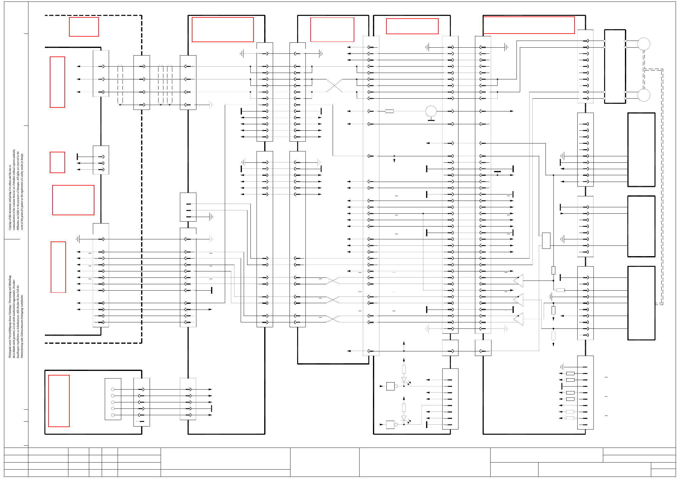
2 - 72
Z03_612X2X3-020101LD3 Z axis, 20-segment C&P head, gantry 3, SIPLACE X2 and X3 (sh. 1 of 2)
+15V 25
1, 10, 34
28
34-pole
PE
+24V
X6ca
19
15
22
16, 31
7
GND
-15V
+5V
Z sensor stop
+15V25
34-pole
+24V
1, 10, 34
X6cc
PE
28
Z sensor stop
+5V
-15V
GND16, 31
19
22
15
7
Gantry 1 or 3
03010612 (ca)
Cable carrier interface
Cable carrier interface
GN
WH
43
X22
42
GN
WH
03009803
Z1 motor
Z motor V
Z motor U
2
1
X14ca
Z1/DP1 motor
03038077
Carrier cable 7, 1G
2
3
5
4
1,8,9,10,34
34-pole
PE
X7ca
Z motor V
Z motor U
3
5
4
2
34-pole
PE1,8,9,10,34
X7cc
LOGIC
"Z axis bottom"
VCC
R61
VCC
R60
R59
X1cs:32
X1cs:33
X1cs:35
X1cs:36
X1cs:39
X1cs:38
GND
VCC
LSM 3
E_LIS_Z_
OBEN_SP
H6 green
VCC
LSVZ
LSVA
GND
LZOS
LSZD
7
8
6
4
5
31 Z track AZ track A
Z track A
LO-RESET
E_LIS_Z_
UNTEN_SP
Document st.
Product st.
Function st.
1. Hi
Hi1.
Hi2.
Z03_612X2X3-020101LD3
10.07.06
10.07.06
10.07.06
11.01.2005
Copyright reserved
SIEMENS AG
Gantry 3
SIPLACE X2 and X3
Gantry 3
03000901 (cc)
Head interface
X13cc:48
PE
Key
BU
RD
PK
OG
WH
03046225 (qa)
Main distributor
+24V
0V
+5V
+15V
-15V
n.u. 13
X1qa
n.u. 14
Z sensor stop
Z track A
Z track A
Z track B
Z track B
Z track N
Z track N
Sheet 2
8
+5V 12
11
OPTO_GND 10
9
6
5
2
3
1 WH (W1) +24V1
n.u.
BN
GN
41
6
5
2
3
2
(W2)
(W2)
(W1)
(W1)
GND4
5 +5V
3
2
+15V
-15V
n.u.13
Cable carrier interface
X5qa
Voltage
03009808
X50ca
2
3
4
X13cs
1
2K2
10
9
8
Key
GY Track B
00321221
WH1GND
AGND0R
2K2
R62
4
6
5 GN
3
2
BN
0R
X4cs
8
7
Key
GND
Track A
Track N
Incremental
Output
SP6-12 intermediate distributor board, digital
Z motor V Z motor V199 Z motor V88
E_LIS_Z_UNTEN_SP
GND
DP tachom. -
DP tachom. +
DP track N
DP track N
DP track B
DP track B
DP track A
X8cc:29
X8cc:33
X8cc:26
X8cc:30
VCC
15
21
83, 85
19
25
VCC
X8cc:24
X8cc:27
X8cc:23
27
23
29
GND
GND
n.u.
"Z axis bottom"
Light barrier
Z clamping
Z motor V2
60
X13cc:49
X8cc:15
139
81
101
E_LIS_Z_OBEN_SP
Sensor stop
n.u.
Light barrier
"Z axis top"
DG
2
SV1
1
GND1515
X2cs:22
n.u.
GND
GND
n.u.
DP track N
DP track N
DP track A
DP track B
DP track B
25
26
24
22
23
21
25
26
24
22
23
21
18
19
20
16
17
18
19
20
16
17
VCC
"Z axis top"
n.u.
Sensor stop
Reference point
Forced air valve
X6cs:1
n.u.
14
13
12
14
13
HI
12
10
11
9
10
11
9
DLM-X head adapter
DP motor U
DP motor W
DP motor V
Z motor W2
Z motor W1
Z motor U2
Z motor U1
102,104
Z motor W
X8cc:3,4
Z motor U
105
97
95
103
X22cc/J3
X8cc:2
X8cc:5
106
100
03019066 (cq)
PE
n.u.
n.u.
n.u.
n.u.
AGND
Z motor W
5
7
6
4
3
5
7
6
4
3
03004333-W1
1
2
X14cq X1cs
1
2
00330648 (cs)
37
WH
Interference suppression board
Z tachom.+ 9WH
VCC +5V8
AGND
GND
ENABLE
Key
5
6
4
2
3
1
+15V
X11cs
9
10
+15V
GND
00321524
Light barrier
Output
+15V
2
AGND
GND
5
7
6
4
3
Z tachom.-
X10cs
1
10 BU
AGND
GND
00347297
"Z axis top"
Light barrier
BU
4
ModifiedStatus Date
CAD file : Z03_612X2X3-020101LD3_SH01.DWG
Orig./Repl.f./Repl.byStand.Name
Check.
Mat. no. :
Author Hi
Date
Sh.
Sh.
SIPLACE X-Series
1
2
Z axis, 6/12-segment Collect&Place head
8
T
00321220
Key
6
8
7
Key
5
4
Z motor V
Z motor W
X3cs
2
3
1
BK
RD
Z motor 03014578
BK
RD
1
2
5
6
M
Not used
n.u.
n.u.
n.u.
n.u.
n.u.
n.u.
n.u.
n.u.
n.u.
n.u.
n.u.
n.u.
n.u.
n.u.
n.u.
14 n.u.
Z track N8
Z sensor stop
Z track N
12
11
+5V
10
9
GND
Z track A
Z track A
Z track B
Z track B
6
5
2
3
PE
32 Z track A32
Carrier cable 6, 1G
03038076
S/Z2 motor
33
Z track A33
26
30
29
27
24
23
Z track N26
Z track B
Z track B
Z track N
29
30
27
Z tachom.+
Z tachom.-
24
23
03044425-W3
BN
RD
BK
Phase_W BN3
Sheet 2
6
Backplane
Axis unit
03039648 (sq)
X1up /
1,4,7,17,20,23,26
X08_1sq
26-pole
GND
X22_4sq10-pole
1,4
5
03042047
Axis unit
Sheet 2
X3uy /
X08_3sq
Phase_V 2
Phase_U 1
RD
BK
BNBN44 Z motor W3 6 Z motor W6
1,4,7,17,20,23,26
03009814
Actual value
Z1 axis
Z tachom.+1
26-pole
Z tachom.-
X24ca
3, 4
2
PE
X141
BK
41 BK 4 PE
GND GND16, 31 16, 31
19
28
25
22
+15V
+24V
-15V
+5V +5V
+24V
+15V
-15V
25
28
19
22
CS_A*
Z track A
137
33
H5 green
VCC
LZUS
VCC
X9cq:19
PE
DP track A
Z tachom.+
Z tachom.-
Z track N
Z track N
Z track B
Z track B
39Z track N
Z track B
Z track B
Z track N
35
37
41
+15V
X8cc:32
-15V
88, 90
43
+15V
87, 89
45
17
-15V
GND
3
Z track A38 38
RESET)
"Z axis bottom"
(Light barrier
LO-RESET
Z track A
AGND
03004333-W2
1
2
TP
X13cq
13
40
39
X2cs
13
40
39
2
Track A
GND
Z track B
Z track B
VCC
Z track N
Z track N
Z tachom.+
Z tachom.-
-15V
+15V
DP track A
3232
35
37
36
34
33
35
37
36
34
33
31
30
28
29
27
31
30
28
29
27
11
Track N
13
14
10
Track B
5
Track B
Track B
Track N
Track N
Ω6x470
n.u.
+5V
9
10
8
6
7
YE
angular position encoder
+5VVCC 7
GND
Z-axis track signals
Test plug
Track A
Track A
AGND
See page 5-41
See page 4-7
See page 5-28
See page 5-46
See page 5-7
See page 5-57
See page 4-9