X4电路图.pdf - 第186页
2 - 131 DPTH012_X 2-02010 1LD3 DP2 axis, TwinHead, P&P modul e 2, gant ry 1, S IPLACE X 2 (sh . 1 of 3) Modified Status Date CAD file : DPTH012_X2-020101LD3 _SH01.DWG Orig./Repl.f./Repl.by Sta nd. Name Check. Mat. no…
2 - 130
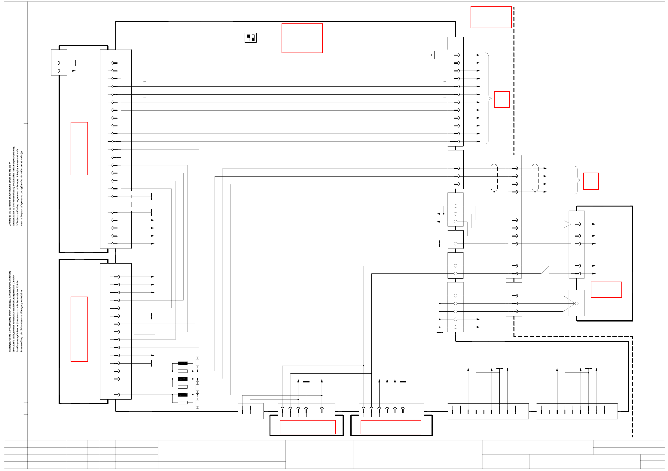
DPTH011_X2-020101LD3 DP1 axis, TwinHead, P&P module 1, gantry 1, SIPLACE X2 (sh. 3 of 3)
AGND
-15V
+15V_Servo
+5V
X4sc
A1
A4
AGND End signal
03036027 (sc)
Axis card A364, gantry 1 SDS60/1D1 servo amplifier
03002142 (sq)
Track A
Track A
Track B
Track B
Track N
Track N
OPTO_GND
UB_Power_OK
Inom_W
Inom_U
+15V_Servo
-15V_Servo
Servo_Ready
AGND
Inom_W
Inom_U
Servo_Enable
+40V_Z/DP
UB_Power_OK
+150V_Star
Phase_V
Phase_U
Phase_W
A8
C7
Servo_Enable
Servo_Ready
I²t
PGND
C22; A/C24
C16 I²t
35
36
37
38
X21
1
2
3
03044424-W2
BK
RD
BN
BK
RD
BN
Phase_U
Phase_V
Phase_W
D22
+15V_Servo
-15V_Servo
+5V
+15V
-15V
D10,18
D30
Z28
Z20;D22
Z4; D6
D30
D10
Z28
Z16;D18
D6
-15V
+15V
2
1
8
X30_1sq
1
3
2
4
5
6
7
Powerfail_24VDC
PA1_CAN_L
GND
PA1_CAN_H
9
n.u.
n.u.
n.u.
n.u.
9
n.u.
1
5
n.u.
n.u.
7
8
6
n.u.
3
4
2
X30_2sq
PA2_CAN_H
PA2_CAN_L
Powerfail_24VDC
GND
2
X45sq
1
3
X40sq
4
2
X46sq
1
5
4
X41sq
3
2
1
X22
1
2
3
GY
GY
GY 10+11
8+9
6+7
03009807
3 (W1)
4 (W1)
23
25GY
BK
Vin-
Vin+
4 (W1)
3 (W1)
16WH 2 (W1)
11
14
13BN
BN
VT
1 (W2)
2 (W2)
1 (W1)
03009786
7
4
1
X13
9
6
Vin(+)Axis
Vin(-)Axis
X12
0V
1 (W2)
2 (W2)
1 (W1)
2 (W1)
N40V
P40V
+150V_Star
12-pole
Power supply
00354626
DC/DC converter 5V/±15V
00353449
DC/DC converter ±15V
00353450
X49sq
X51sq
X50sq
PGND
Z4,8,20
Z8,16
GND
AGND
PGND
+40V_Z/DP
+150V_Star
R16
L7
R17
L8
R18
L9
X09_1sq
WH
GN
BN
BK
Sheet 2
X16ba
Document st.
Product st.
Function st.
1. Hi
Hi1.
Hi2.
DPTH011_X2-020101LD3
10.07.06
10.07.06
10.07.06
11.01.2005
Copyright reserved
SIEMENS AG
OFF
ON
S1
12
26-pole
6
12
13
14
10
9
8
3
5
2
X3tp /
Axis unit
03039648 (sq)
Backplane
1,4,7,17,20,23,26
PE
(S1.2 n.u.)
11
A/D4; B/E1,2,4; C1,6
C3
B/E8
C14
C13
B13
A13
B11
A12
B12
X23_1sq
A11
X1sc
A14
A10; B9
A9
A2
B7
A7
A1
A/C/E15,18,19,22,23
B10
B/D15-17,20,21,24,25
Axis unit
Gantries 1 and 3
X09_2sq
A/C32
A/C30
C26; A/C28
C10
C18; A/C20
C14
C12
A12
A8
C8
A/C2
C4
A4
X1sq
GND
X26ba
Sheet 2
DP1 motor_W
Screen
DP1 motor_U
DP1 motor_V
C4 +15V
OPTO_GND
Track N
Track N
Track A
Track B
Track B
Track A
+5V
n.u.
n.u.
n.u.
X09_3sq
X3tz /
DP1 axis, TwinHead, P&P module 1
Gantry 1
03009795
03009785
SIPLACE X2
n.u.
+5V
n.u.
n.u.
X44:1
X43:1
GY
GY
03042047
ModifiedStatus Date
CAD file : DPTH011_X2-020101LD3_SH03.DWG
Orig./Repl.f./Repl.byStand.Name
Check.
Mat. no. :
Author Hi
Date
Sh.
Sh.
SIPLACE X-Series
3
3
See page 5-57
See page 4-7
See page 5-55
See page 4-11
See page 3-7
See page 5-12
See page 5-13
2 - 131
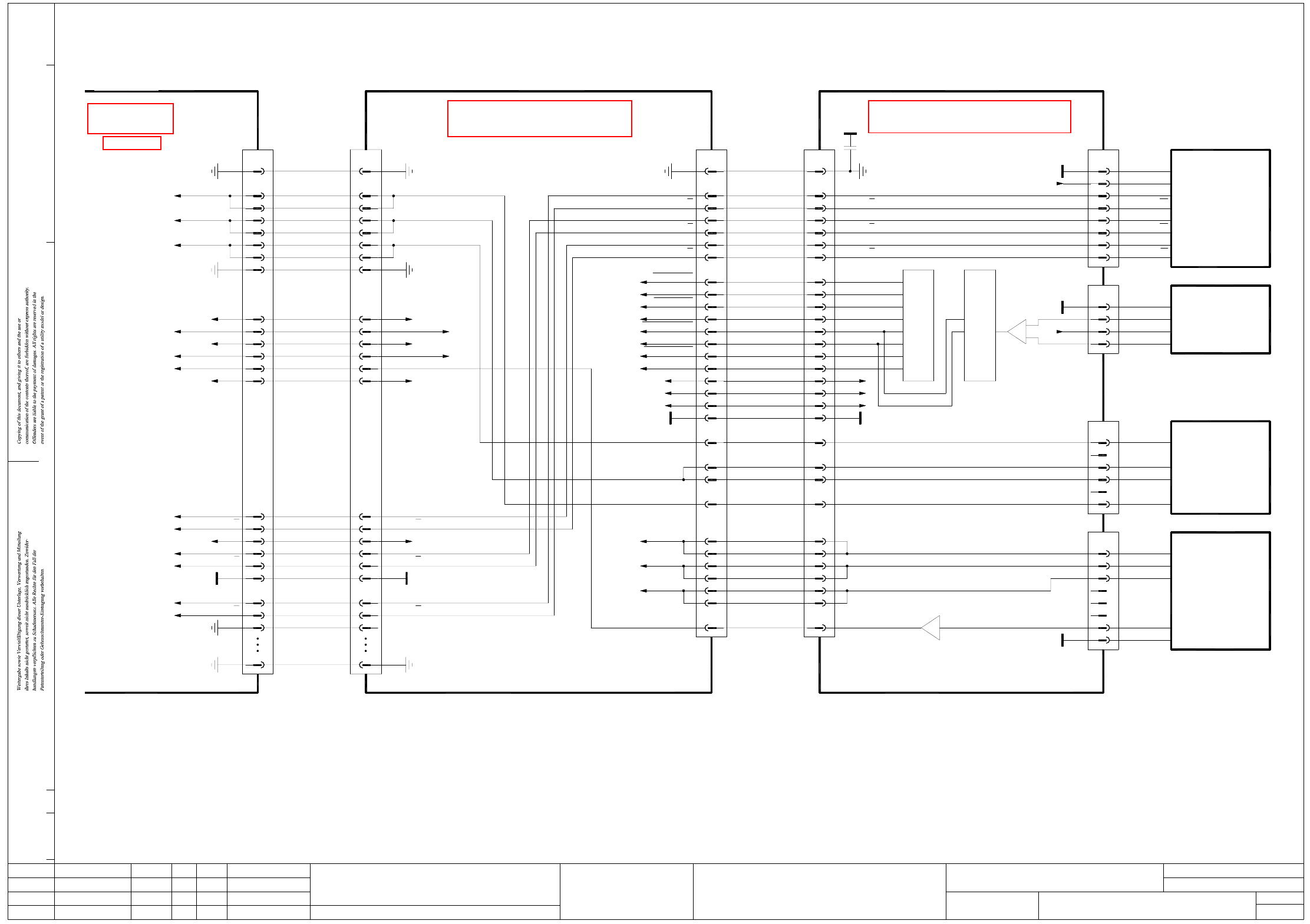
DPTH012_X2-020101LD3 DP2 axis, TwinHead, P&P module 2, gantry 1, SIPLACE X2 (sh. 1 of 3)
ModifiedStatus Date
CAD file : DPTH012_X2-020101LD3_SH01.DWG
Orig./Repl.f./Repl.byStand.Name
Check.
Mat. no. :
Author Hi
Date
Sh.
Sh.
SIPLACE X-Series
1
3
Document st.
Product st.
Function st.
1. Hi
Hi1.
Hi2.
DPTH012_X2-020101LD3
10.07.06
10.07.06
10.07.06
11.01.2005
Copyright reserved
SIEMENS AG
DP2 axis, TwinHead, P&P module 2
Gantry 1
SIPLACE X2
DP2 motor U
DP2 motor V
DP2 motor W
Z2 temperature sensor
Z2-Force-SCLK
Z2-Force-SCLK
Z2-Force-Dir
Z2-Force-Dir
Z2-Force-CS
Z2-Force-CS
Z2-Force-DATA
Z2-Force-DATA
50
33
34
32
31
30
26
27
29
28
PE
DP2 track A
+24V
GND
DP2 track A
DP2 track B
DP2 track B
DP2 track N
DP2 track N
DP2 track A
50
PE
34
33
n.u.
+24V28
DP2 track A
DP2 track B
DP2 track B
GND31
32
29
30
DP2 track N
DP2 track N
27
26
X31bd:7, 8
X31bd:5, 6
X31bd:3, 4
2
4
5
3
1
7
8
19
21
23
22
6
24
25
X32br
Z2 temperature sensor
Z2 reference point
Key
2
3
GY
BU
Linear drive
Z2 axis
Linear motor
03014681
U-Sensor
C700 TwinHead force meas. board, P&P module 2
DP2 motor W
DP2 track B
DP2 track B
DP2 track A
DP2 track A
DP2 track N
DP2 track N
+15V 17
+5V
GND
20
19
18
-15V
14
16
15
13
12
+15V17
20
19
18
GND
+5V
14
16
15
-15V
13
12
DP2 track N
10
11
9
8
7
DP2 track B
DP2 track N
DP2 track B
DP2 track A
DP2 track A
5
6
4
2
3
10
11
9
8
7
5
6
4
2
3
2
1
2
6
7
1
-
+
3
9
10
14
15 J13 J12
Force sensor
DP unit control cable
03005289
X8bd
PE 1
X8be
1PE
00352809 (be)
C37
220n
+5V
+5V2
Force transducer
U-Sensor +
OUT -
B- (W)
X16be
Key
5
6 YE
4
3
DISC-Magnetic-Motor
03000100
OUT +
RI
RI
T1
T2
T2
T1
X15be
GND 1
2
8
6
7
5
3
4
Z2 clamping
+15V
-15V
VCC
PE
DP2 motor W
DP2 motor V
DP2 motor U
P&P head adapter
03000902 (br)
Sheet 2
PE
Z2 temperature sensor
Z2 clamping
Z2 reference point
23
24
25
+15V
21
22
-15V
19 VCC
7
8
PE
DP2 motor U
DP2 motor V
DP2 motor W
4
5
6
3
X31bd:18
X5bd:4
X31bd:20
X31bd:21
X31bd:24
X31bd:23
X31bd:14
X31bd:15
X31bd:17
Twin flat ribbon cable loom
03004332-W3
1
X30bd
PE
00352833 (bd)
C600 head main board, P&P module 2
BN B+ (V)
P310.822
4DP2 motor V22121
Z2 temperature sensor
Z2 motor W
Z2 motor U
Z2 motor V
DP2 motor V1
DP2 motor U
30 30
Z2 motor U 24
Z2 motor W
Z2 motor V
27
28
29
25
26
23
22
24
27
28
29
25
26
23
22
00353135
Key
GND
Key
7
8
6
BN
YE
Temperature sensor
A- (V)
A+ (U)
X17be
3
Key
4
5
1
2
BU
WH
GY
1
03000046
Encoder
Pick&Place module
GND
X18be
GND 1
PE
U-Sensor -
2
See page 5-30
See page 5-11
See page 5-10
2 - 132
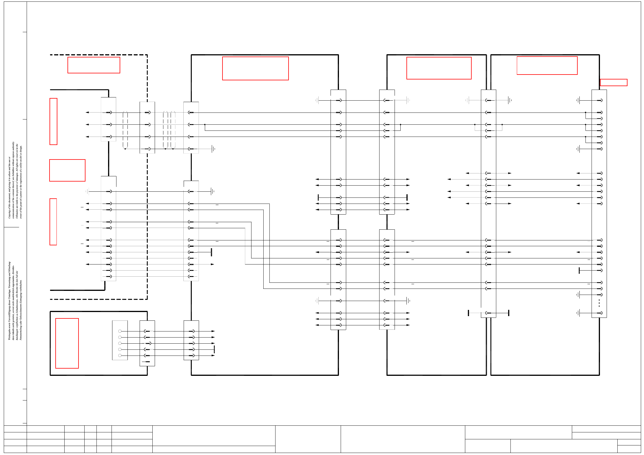
DPTH012_X2-020101LD3 DP2 axis, TwinHead, P&P module 2, gantry 1, SIPLACE X2 (sh. 2 of 3)
GND
+24V
36
34
32
40
38
84,86
42
+24V
50PE
DP2 track B 30
31
32
34
33
DP2 track A
DP2 track A
PE
GND
28
29
27
26
DP2 track N
DP2 track B
+24V
DP2 track N
03038078
28
16,31
25
19
22
+15V
+24V
GND
25
28
16,31
VCC
-15V
22
19
Carrier cable 8, 1G
DP1/DP2 motor
3
4
5
2
1,10,14,34
X8ba
DP2 motor V7
DP2 motor W
9
8
DP2 motor U6
1,10,14,34
X8bc
PE
Z2 temperature sensor
Z2 reference point
+15V
X5bc:15
X6bc:14
88,90
26
+15V
-15V 87,89
51
66
VCC 83,85
-15V
VCC
94
93
96
98
X22bc/J3
PE 91,92
PE
Head interface
03000901 (bc)
Gantry 1
Z2 reference point
Z2 temperature sensor
24
25+15V
19
21
22
23
-15V
Z2 clamping
VCC
DP2 motor W
DP2 motor V
DP2 motor U
4
7
PE 8
6
5
X32br
3
2
PE 1
From sheet 1
P&P head adapter
03000902 (br)
34-pole34-pole
34-pole 34-pole 140-pole
X6bc:15
Z2 clamping
Document st.
Product st.
Function st.
1. Hi
Hi1.
Hi2.
DPTH012_X2-020101LD3
10.07.06
10.07.06
10.07.06
11.01.2005
Copyright reserved
SIEMENS AG
DP2 axis, TwinHead, P&P module 2
Gantry 1
SIPLACE X2
+24V
-15V
+15V
PE
VCC
-15V
DP2 motor U
DP2 motor V
DP2 motor W
DP2 track N
DP2 track N
DP2 track B
DP2 track B
DP2 track A
DP2 track A
+15V
+24V
+24V
GND
PE
Sheet 3
DP2 track B
X1qa
Main distributor
03046225 (qa)
+5V
+15V
0V
-15V
+24V
DP2 track N
DP2 track N
12+5V
n.u.
n.u.
14
13
n.u.
OPTO_GND
9
11
10
8
-15V
+15V
GND
+5V
+24V
Voltage
03009788
Cable carrier interface
2BN2(W1)BU
PK
RD
WH
5 25(W2)
n.u.
66
GN33
441
(W1)
(W2)
X6qa
OG WH1(W1)
2
5
3
4
X50ba
1
12 +5V
14
13
n.u.
n.u.
9
11
10
8
DP2 track N
n.u.
GND
DP2 track N
BK
03044424-W1
1,4,7,17,20,23,26
Axis unit
Backplane
03039648 (sq)
DP2 track A
DP2 track A
DP2 track B
5
6
2
3
26-pole
PE
X5tp/
X10_1sq
Sheet 3
RD2Phase_V
Phase_W 3 BN
Phase_U
X10_3sq
1
X3tw/
Axis unit, gantries 1 and 3
03042047
03009783
03009796
Actual value
DP2 axis
5
6
2
3
DP2 track B
DP2 track B
DP2 track A
DP2 track A
1,4,7,17,20,23,26
X25ba
26-pole
PE
DP2 motor
Cable carrier interface
GN31RD
29
BN 32
BK
BN
X22
BK
30 WH
2DP2 motor VGN
BK
4
BN 3
PE
DP2 motor W
X15ba
WH
1DP2 motor U
Gantry 1 or 3
Cable carrier interface
03010612 (ba)
03038077
1,8,9,10,34 1,8,9,10,34 PE
25
28
22
+24V
-15V
+15V25
28
22
Z/DP1 motor
Carrier cable 7, 1G
30
32
33
27
28
29
26
X7ba
DP2 track B30
DP2 track A
DP2 track A
32
33
DP2 track N
DP2 track N
DP2 track B
+24V
27
29
28
X7bc
26
GND
7,13,134,140
ModifiedStatus Date
CAD file : DPTH012_X2-020101LD3_SH02.DWG
Orig./Repl.f./Repl.byStand.Name
Check.
Mat. no. :
Author Hi
Date
Sh.
Sh.
SIPLACE X-Series
2
3
See page 4-7
See page 5-41
See page 5-28
See page 5-30
See page 4-9
See page 5-57