X4电路图.pdf - 第181页
2 - 126 ZTH032_X2X3-02 0101LD3 Z2 axis, T winHead, P&P module 2, g antry 3, SIPLACE X2 and X3 (sh . 2 of 3) -15V +24V 26 20 24 25 23 21 22 17 18 19 15 16 n.u. Z2-Forc e-CS Z2-Forc e-CS Z2-Dir 03044425-W4 Sheet 3 Z2 t…
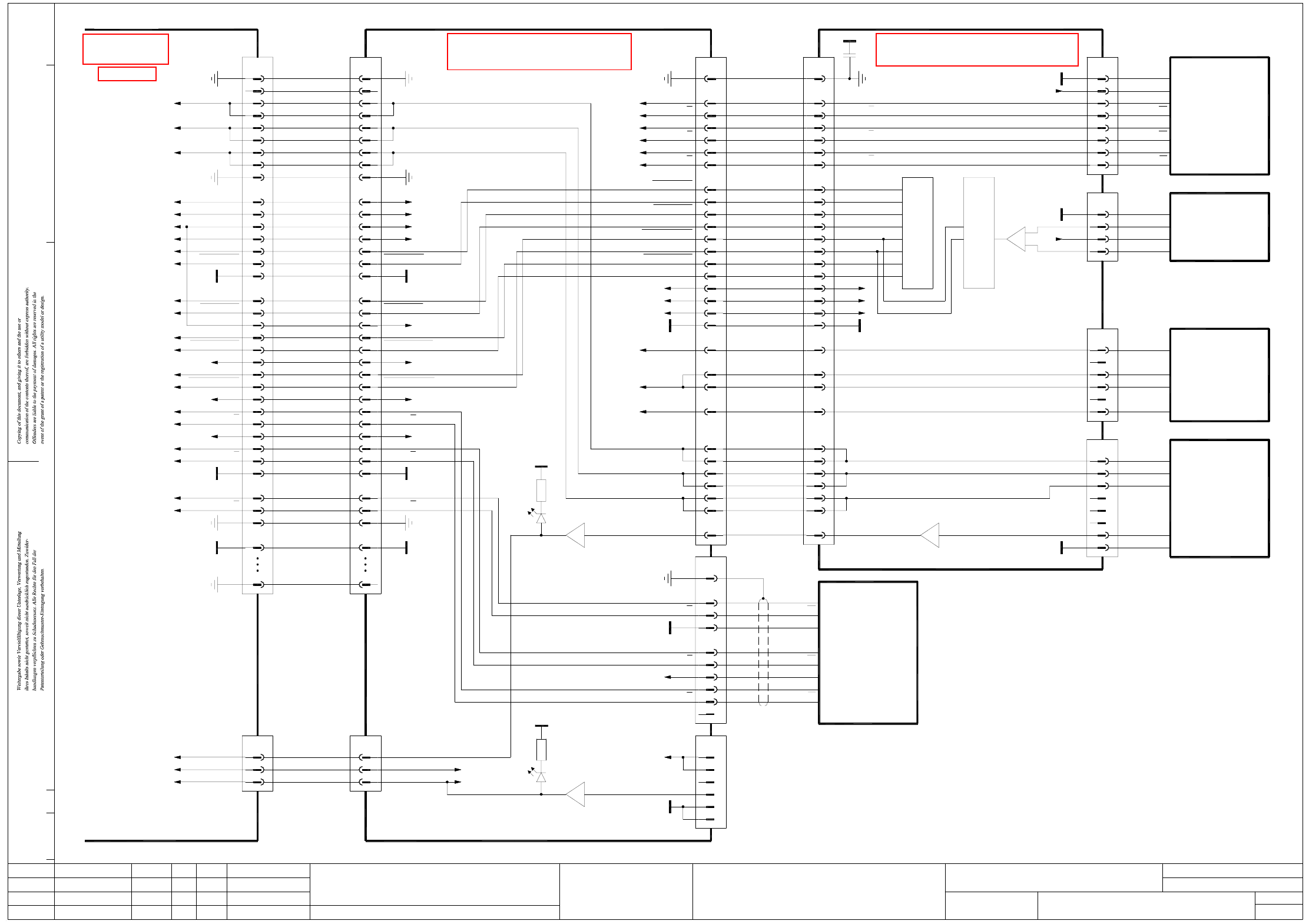
2 - 125
ZTH032_X2X3-020101LD3 Z2 axis, TwinHead, P&P module 2, gantry 3, SIPLACE X2 and X3 (sh. 1 of 3)
U-Sensor -
Key
+5V
GND
50-pole 50-pole
GND
GND
Document st.
Product st.
Function st.
1. Hi
Hi1.
Hi2.
ZTH032_X2X3-020101LD3
10.07.06
10.07.06
10.07.06
11.01.2005
Copyright reserved
SIEMENS AG
Gantry 3
SIPLACE X2 and X3
Z2 reference point
DP2 motor U
DP2 motor V
DP2 motor W
Z2 temperature sensor
Z2-Force-SCLK
Z2-Force-SCLK
Z2-Force-Dir
Z2-Force-Dir
Z2-Force-CS
Z2-Force-CS
Z2-Force-DATA
Z2-Force-DATA
21
23
24
X32cr
50
33
34
35
32
31
Z2 temperature sensor
Z2 reference point
Z2 clamping
PE
Z2 track A
PE
Z2 track A
GND
Z2 temperature sensor24
Z2 clamping
Z2 reference point
23
21
D6X2cd:78 green
Twin flat ribbon cable loom
03004332-W3
X30cd
n.u.
35
50
Z2 track A
Z2 track A
34
33
PE
31
32
GND
V1green
30
2
4
5
3
1
7
10
9
8
13
12
15
14
11
16
18
17
19
20
21
23
22
6
24
26
27
25
29
28
X33cr
PE
VCC
Z2 track B
Z2 track B
+24V
Z2 track N
Z2 track N
+15V
Z2-Force-DATA
Z2-Force-DATA
Z2-Force-SCLK
Z2-Force-SCLK
-15V
Z2-Force-Dir
Z2-Force-CS
Z2-Force-CS
GND
Z2-Force-Dir
Gantry-ID-Bit 2
Gantry-ID-Bit 1
Gantry-ID-Bit 0
Power-Fail
P&P head adapter
03000902 (cr)
Sheet 2
Z2 motor W
Z2 motor V
Z2 motor U
Key
PE
PE9
+5V19
Z2 track B
Z2 track B
Z2 track N
Z2 track N
29
30
28
+24V
27
26
25
+15V
Z2-Force-SCLK
Z2-Force-SCLK
Z2-Force-DATA
Z2-Force-DATA
-15V22
23
24
20
21
Z2-Force-Dir14
Z2-Force-CS
Z2-Force-CS
Z2-Force-Dir
17
18
15
16
GND
P&P-Head-ID-Bit
Power-Fail
Gantry-ID-Bit 1
Gantry-ID-Bit 0
11
12
13
10
X30cd:4, 5
X30cd:2, 3
X30cd:6, 7
Twin flat ribbon cable loom
03004332-W4
Z2 motor V
Z2 motor W
6
7
8
4
5
Z2 motor U
X31cd
2
3
1
n.u.
PE
00352833 (cd)
C600 head main board, P&P module 2
X30cd:32
X30cd:30
X30cd:27
X30cd:26
X30cd:29
X30cd:33
+5V 1
GND 5
6
4
2
Key
3
Scanning head
03000102
Z2 axis
Z2 temperature sensor
Z2 motor W
Z2 motor V
10
X5cd
Key
Z2 track N
Z2 track N 9
8
BN
GY
Z2 track B
Z2 track B 6
7
5
Z2 track A
4
3
PK
RD
BK
YE
WH
RI
RI
GND
+5V
T2
T2
T1
30
X4cd
PE 1
Z2 track A 2
WHGN
GN
Z2 motor W
Z2 motor V
29
27
28
26
30
T1
29
27
28
26
BN7
GND 8 YE
Key
Key
Key
6
5
3
4
2
BU
GY
Temperature sensor
00353135
Z2 axis
Linear drive
Linear motor
U-Sensor
C700 TwinHead force meas. board, P&P module 2
Z2 motor U
DP2 motor W
DP2 motor V1
DP2 motor V2
DP2 motor U
GNDGND 1919
Z2 motor U 24
25
23
21
22
20
24
25
23
21
22
20
13
-15V
+5V
+15V
16
18
17
15
14
10
12
11
9
8
13
-15V16
18
17
+5V
+15V
15
14
10
12
11
9
8
2
3
6
2
1
9
7
10
14
15 J13
-
1
J12
+
DP2 track B
DP2 track B
DP2 track A
DP2 track A
DP2 track N
DP2 track N
Force sensor
DP unit control cable
03005289
DP2 track B
DP2 track N
DP2 track N
DP2 track B
DP2 track A
5
7
6
4
3
X8cd
DP2 track A
PE
2
1
5
7
6
4
3
X8ce
2
1 PE
00352809 (ce)
C37
220n
B- (W)
B+ (V)
A- (V)
A+ (U)
X17ce
1
Key
1
2
WH
GY
X16ce
5
Key
4
3
6
BN
BU
YE
03014681
DISC-Magnetic-Motor
P310.822
OUT +
U-Sensor +
OUT -
4
X15ce
GND
1
3
2
03000100
Force transducer
RI
RI
T1
T2
T2
GND
+5V
T1
6
8
7
5
4
X18ce
+5V
GND
2
3
1
Encoder
03000046
Pick&Place module
ModifiedStatus Date
CAD file : ZTH032_X2X3-020101LD3_SH01.DWG
Orig./Repl.f./Repl.byStand.Name
Check.
Mat. no. :
Author Hi
Date
Sh.
Sh.
SIPLACE X-Series
1
3
Z2 axis, TwinHead, P&P module 2
See page 5-30
See page 5-11
See page 5-10
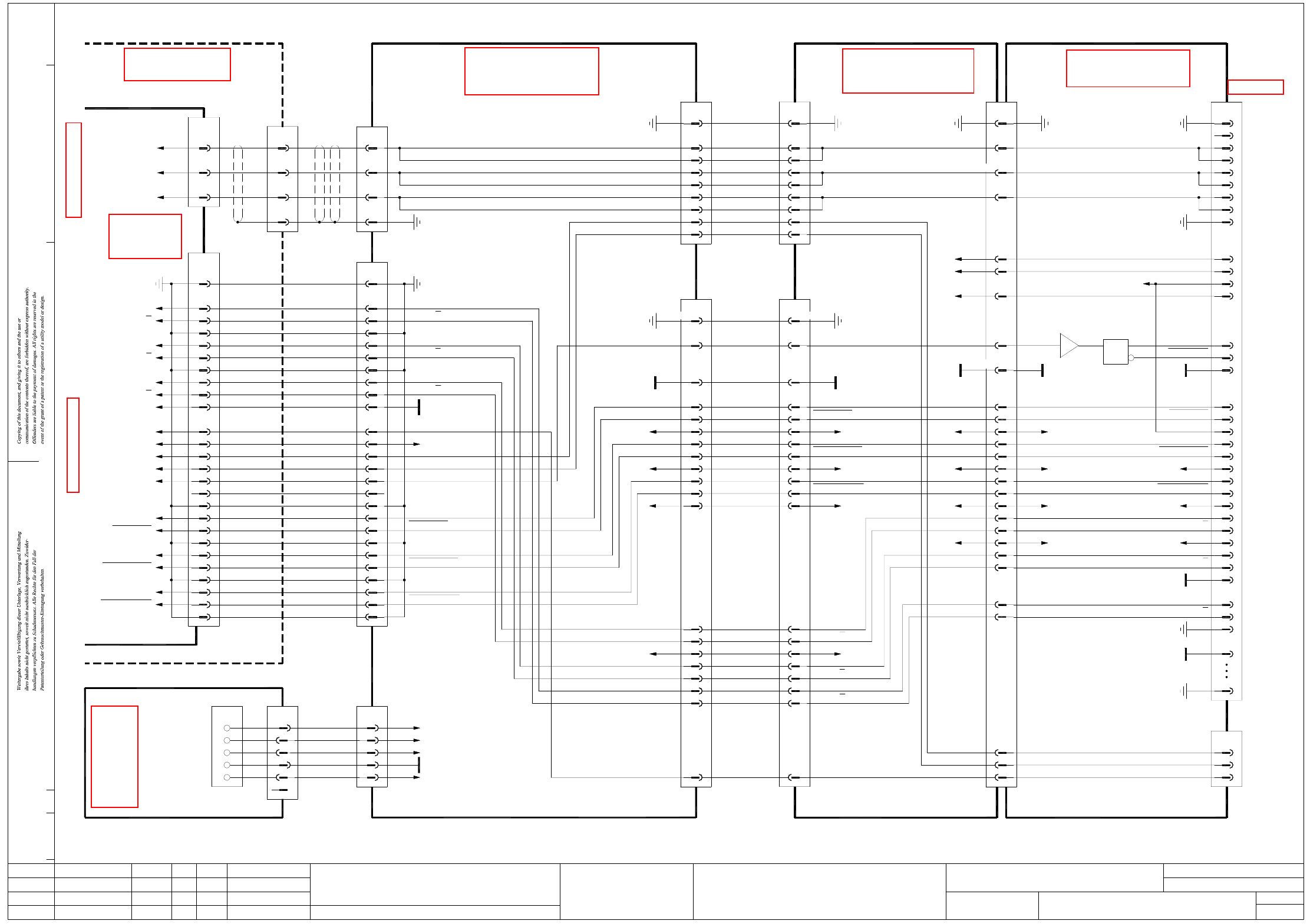
2 - 126
ZTH032_X2X3-020101LD3 Z2 axis, TwinHead, P&P module 2, gantry 3, SIPLACE X2 and X3 (sh. 2 of 3)
-15V
+24V
26
20
24
25
23
21
22
17
18
19
15
16
n.u.
Z2-Force-CS
Z2-Force-CS
Z2-Dir
03044425-W4
Sheet 3
Z2 track A
3
Z2 reference point
Z2 temperature sensor
+5V
Z2 track N
Z2 track N
Z2 track B
OPTO_GND
Z2 track B
9
13
10
12
11
6
8
7
5
4
Backplane
Axis unit
03039648 (sq)
Z2 track A
X5uo/
X07_1sq
PE 1
2
Phase_W 3 BN
X3uv /
X07_3sq
1Phase_U
Phase_V
2
BK
RD
03042047
Axis unit
Z2 reference point
Z2 temperature sensor
Z2 track A3
Z2 track N9
11
13
12
10
+5V
GND
6
8
7
5
4
Z2 track B
Z2 track N
Z2 track B
BK
BN
03009813
Actual value
S/Z2 axis
45
34BN
BK
BN
1PE
2
X23ca
Z2 track A
Z2 motor W
4PE
3
Cable carrier interface
WH
GN
S/Z2 motor
46BK
40RD
X22
WH
GN
03009802
Z2 motor U
Z2 motor V
1
2
X13ca
Gantry 1 or 3
Cable carrier interface
03010612 (ca)
-15V -15V22 22 -15V-15V 87,89 -15V 22
ModifiedStatus Date
CAD file : ZTH032_X2X3-020101LD3_SH02.DWG
Orig./Repl.f./Repl.byStand.Name
Check.
Mat. no. :
Author Hi
Date
Sh.
Sh.
SIPLACE X-Series
2
3
Z2 axis, TwinHead, P&P module 2
GND
66
Z2 temperature sensor
15 15 26
51
Z2-Force-DATA
Z2-Force-DATA
30
33
32
+24V
29
28
26
27
Z2 track B30
33
32 Z2 track A
Z2 track A
29
28
26
27
Z2 track B
+24V
Z2 track N
Z2 track N
+15V 25
23
24
25
23
24
+15V
2
+24V +24V84,86
4
8
6
10
14
88,90
12
16
+15V
+15V
Z2 reference point 21
Z2 temperature sensor
Z2 clamping
24
23
PE 50
X32cr
Z2 track A
PE
34
35
33
Z2-Force-DATA
Z2-Force-DATA
+24V
28
Z2 track A
GND
Z2 track B
Z2 track B
32
31
29
30
+15V
Z2 track N
Z2 track N
25
26
27
23
24
Z2 reference point
Z2-Force-SCLK
Z2-Force-SCLK
PE
1,11,14,34 PE1,11,14,34
+5V 19
21
20
18
17
GND
16,31
Document st.
Product st.
Function st.
1. Hi
Hi1.
Hi2.
ZTH032_X2X3-020101LD3
10.07.06
10.07.06
10.07.06
11.01.2005
Copyright reserved
SIEMENS AG
Gantry 3
SIPLACE X2 and X3
Sheet 3
Z2 clamping1414
Key
WH
Main distributor
+15V
03046225 (qa)
0V
+5V
Z2-Force-DATA
-15V
+24V
X1qa
26
Z2 clamping
Z2-Dir
Z2-Force-DATA
Z2-Force-SCLK
Z2-Force-SCLK
Z2-Force-CS
Z2-Force-CS
20
22
21
25
24
23
19
17
18
16
15
n.u.
3
+15V
3GN3(W1)RD
66
PK 55
44
n.u.
(W2)
(W2)
2
1
5
4
GND
+5V
Z2-Force-SCLK
Z2-Force-SCLK
Z2-Force-DATA
Z2-Force-DATA
Cable carrier interface
X5qa
BU
OG
2
2
1
(W1)
(W1)
BN
WH
Voltage
03009808
X50ca
2
1
12
19
21
20
18
17
+5V
Z2-Force-CS
Z2-Force-CS
16,31
12
GND
Z2-Dir
X motor
Carrier cable 5, 1G
03038075
X5ca
15
14
8
9
6,7
X5cc
15
14
8
9
6,7
Z2 clamping
Z2 motor W
GND
18
20
24
22
83,85VCC
VCC
7,13,134,140
28
GND
Z2-Dir
X13cc:73
X14cc:71
X14cc:73
133
135
1
107,109
03038076
Carrier cable 6, 1G
S/Z2 motor
1,10,34
2
3
4,5
PE
X6ca
1,10,34
2
3
4,5
X6cc
Z2 motor U
Z2 motor V
PE
03000901 (cc)
Head interface
Gantry 3
91,92
111,113
X22cc/J3
108,110,112,114
PE PE
Z2-Force-SCLK
Z2-Force-SCLK
U2
U1
1
I1
3
2
VCC
Z2-Force-CS
Z2-Force-CS
19
21
20
18
17
Z2-Force-Dir
GND
Z2-Force-Dir
15
16
14
Gantry-ID-Bit 2
Gantry-ID-Bit 1
Gantry-ID-Bit 0
Power failure
12
13
11
10
PE
Z2 motor W
9
7
8
6
From sheet 1
P&P head adapter
03000902 (cr)
Z2 motor U
Z2 motor V
PE
Key
3
4
5
1
2
X33cr
26-pole
34-pole34-pole
34-pole 34-pole 140-pole
50-pole
See page 4-7
See page 5-41
See page 5-28
See page 5-30
See page 4-9
See page 5-57
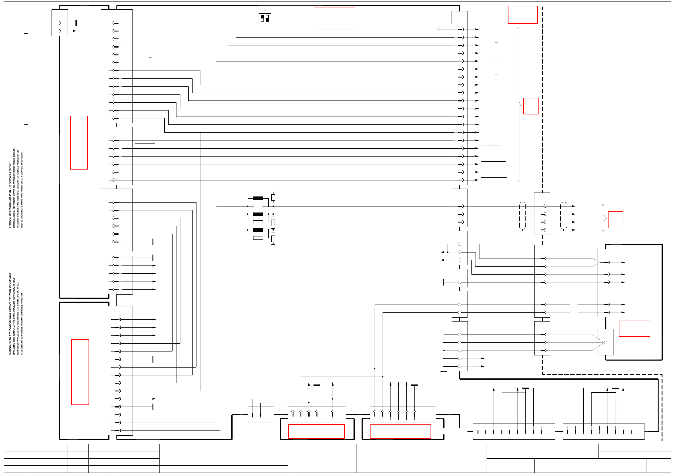
2 - 127
ZTH032_X2X3-020101LD3 Z2 axis, TwinHead, P&P module 2, gantry 3, SIPLACE X2 and X3 (sh. 3 of 3)
ModifiedStatus Date
CAD file : ZTH032_X2X3-020101LD3_SH03.DWG
Orig./Repl.f./Repl.byStand.Name
Check.
Mat. no. :
Author Hi
Date
Sh.
Sh.
SIPLACE X-Series
3
3
Z2 axis, TwinHead, P&P module 2
X22
Z2-Force-SCLK
Z2-Force-CS
Z2-Force-CS
Z2 temperature sensor
Z2 clamping
Z2 reference point
19
22
21
18
16
n.u.
15
14
13
12
Z2-Dir
+5V
X23ca
Sheet 2
1,4,7,17,20,23,26
26-pole
PE
Act. value, S/Z2 axis
03042047
X5uo/
Z2 track N
Z2 track N
Z2 track B
Z2 track B
Z2 track A
Z2 track A
9
10
8
6
OPTO_GND
2
5
3
X07_1sq 03009813
PE
Axis unit
S/Z2 motor, cable carrier interface
Z2 motor_W
BN
BK
GN
WH
Screen
Z2 motor_V
Z2 motor_U
03009802
X13ca
Sheet 2
X43:1
X44:1
GY
GY
Document st.
Product st.
Function st.
1. Hi
Hi1.
Hi2.
ZTH032_X2X3-020101LD3
10.07.06
10.07.06
10.07.06
11.01.2005
Copyright reserved
SIEMENS AG
Gantry 3
SIPLACE X2 and X3
DC/DC converter ±15V
Z4; D6
+15V
Backplane, axis unit
03039648 (sq)
A/C/E3,4,7,8,11
X07_2sq
B/D1,2,5,6,9-11
A/D22; B/E22,24,25; C20,25
03002141 (sq)
SDS60/3Z1 servo amplifier
A/C30
A/C32
C22; A/C24
C26; A/C28
C18; A/C20
C16
X1sq
C8
C14
C12
C10
A12
A8
C4
A4
A/C2
C23
C22
C12
B/E18
Phase_U
Phase_W
Phase_V
+150V_Star
I²t
PGND
+15V
-15V
2
X49sq
1
00353450
Z20;D22
-15V
D30
Z28
Z8,16
D10,18
AGND
Servo_Ready
Servo_Enable
Inom_W
Inom_U
AGND
UB_Power_OK
-15V_Servo
+40V_Z/DP
+15V_Servo
+15V
-15V
+5V
+15V_Servo
AGND
GND
X22_2sq
X22_3sq
X22_3sq
A19
Axis card A364, gantry 3
A25
A16; B17
B16
A17
A24
X3sb
D16
D15
03036027 (sb)
B16
E20
E21
B15
X2sb
C24
A18
C19
AGND
X4sb X3sb
C4
C1
A13
B19
A12
C13
B13
End signal
A14
B14
B15
A15
Z2 reference point
Inom_U
Servo_Ready
Servo_Enable
UB_Power_OK
Inom_W
Z2-Force-DATA
Z2-Force-DATA
Z2-Force-SCLK
Z2-Force-CS
Z2-Force-CS
Z2-Force-SCLK
Z2-Dir
I²t
Z2 clamping
R35
L16
L18
R36
R34
L17
Z2 track N
Z2 temperature sensor
OPTO_GND
+5V
Z2 track N
Z2 track B
Z2 track B
Z2 track A
Z2 track A
S1
ON
(S1.2 n.u.)21
OFF
X45sq
1
DC/DC converter 5V/±15V
X51sq
D30
Z28
00353449
GND
-15V_Servo
+15V_Servo
D10
Z16;D18
D6
+5V
Z4,8,20
D22
X50sq
n.u.
n.u.
9
8
n.u.
n.u.
PA1_CAN_H
GND
PA1_CAN_L
Powerfail_24VDC 4
6
7
5
3
2
PGND
PGND
+40V_Z/DP
+150V_Star
Vin+ BK 23
2
3
4
5
1
2
X41sq
GY 3
GY 1
GY 2
X22
X40sq
Vin- 1
X46sq
4
3
2
1
GY 25
WH 16
BN 13
BN
VT
14
11
X21
PA2_CAN_H
n.u.
n.u.
9
X30_1sq
7
8
6
GND
Powerfail_24VDC
PA2_CAN_L
n.u.
n.u.
4
5
3
2
1
X30_2sq
Vin(-)Axis
94 (W1)3 (W1)
10+11
03009807
6+7
8+9
Power supply
X12
0V
00354626
12-pole
4 (W1)
2 (W1)
3 (W1)
2 (W1)
03009786
1 (W2)
1 (W1)
2 (W2)
1 (W2)
1 (W1)
2 (W2)
P40V
6
7
Vin(+)Axis
N40V
X13
4
1
+150V_Star
11
Phase_W
Phase_V
Phase_U
Z2-Force-SCLK
Z2-Force-DATA
Z2-Force-DATA
03044425-W4
3
2
1
BN
RD
BK
X07_3sq
X3uv /
25
24
BN 34
45
RD
BK
40
46
See page 5-57
See page 4-7
See page 5-55
See page 4-11
See page 3-7
See page 5-12
See page 5-13