YSi-V_Ope_E.pdf - 第109页
S-1 INDEX Index Safety instructions Cautions during power outage iv Cautions regarding ferromagnetic fields iv CE marking i Components and materials to be used x Handling batteries ix Handling grease and oil ix Handling h…
A-9
Appendix
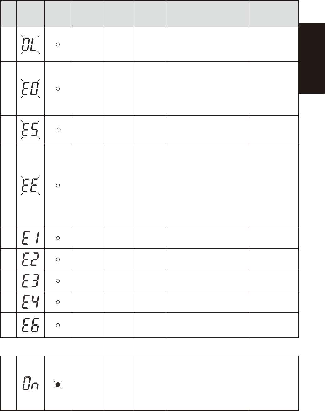
Displays and beeps when equipment failure has occurred
No.
Status
display
Battery
replacement
indicator
lamp
Beep Output Charging Description Solution
11
Intermittent
0.5-second
intervals
ON
ON or
discharging
There are too many connected
devices and the rated capacity is
exceeded. If this status continues
for 5 minutes or more, the status
No. 12 occurs and output stops.
Reduce the number
of connected
devices until the
display appears as
in status No. 3.
12
Continuous OFF
ON or
discharging
Stopped due to excess connection
capacity. If the connection
capacity exceeds 120%, this
status immediately occurs without
entering the status No. 11.
Turn OFF this unit
and all connected
devices. Reduce
the number of
connected devices,
and then turn ON
this unit and the
connected devices.
13
Continuous OFF
ON or
discharging
Output stopped due to short-circuit
with the connected devices.
Check that the AC
input of connected
devices is not short-
circuited.
14
Continuous OFF – Stopped because of failure.
Turn OFF this unit
and all connected
devices. Then, turn
the power switch
back ON for this unit
only. If the display
does not change,
there is a problem
with the UPS.
Contact our
sales office or
representative.
15
Continuous OFF –
Stopped because of excessive
output voltage (over).
(Same as above.)
16
Continuous OFF –
Stopped because of insufficient
output voltage (under).
(Same as above.)
17
Continuous OFF –
Stopped because of excessive
battery charge voltage (over).
(Same as above.)
18
Continuous OFF –
Stopped because of insufficient
battery charge voltage (under).
(Same as above.)
19
Continuous OFF –
Stopped because of abnormal
internal temperature.
(Same as above.)
Displays and beeps for battery replacement
20
Intermittent
2-second
intervals
ON ON
The battery test detected a weak
battery.
Charge the battery.
You can replace
the weak battery
with a separately
purchased
replacement battery
as needed.

S-1
INDEX
Index
Safety instructions
Cautions during power outage iv
Cautions regarding ferromagnetic fields iv
CE marking i
Components and materials to be used x
Handling batteries ix
Handling grease and oil ix
Handling heavy objects ix
Handling solvents vii
Handling the laser viii
Lock out the main switch and the air supply/
exhaust switch iii
Muzzle plate vi
Operator and service personnel iii
Safety ii
Safety message and categories xi
Typical warning text xii
Warning labels xv
3D projector 1-9
4D angular camera 1-10
A
Alarm buzzer 1-1
Axis configuration 1-5
C
Connection between machines A-2
Consumable parts 4-6
Conveyor unit 1-4
Conveyor unit setup 3-4
E
Emergency stop button 1-1
Canceling emergency stop 2-1
Error
Clearing an error 2-1
H
High-speed dual lane 1-11
I
Inspection program 3-3
L
Laser height sensor 1-8
Lubrication of each unit 5-2
M
Machine-to-machine connection
connectors 1-3
Main switch 1-2,2-2
Maintenance 4-2
Air filter 4-25
Ball screws and guides 4-12
Board sensor 4-10
Camera lighting unit 4-17
Importance of periodic inspections and
cleaning 4-3
Monthly 4-11
Replacing the conveyor belts 4-27
Three-month inspection 4-18
Weekly inspection 4-10
Maintenance list 4-4
Maintenance tools 4-7
Manual contents i
Contents of each chapter ii
Page layout iii
Using this manual i
Marker pen 1-7
Marking unit 1-7
O
Operation
Daily operation flow 3-1
Ending 2-3
Pre-operation inspection 2-2
Return-to-origin 2-2
Selecting a board 3-3
Starting 2-2
Option units 1-7
P
Power connection terminals 1-3,A-1
Pressure gauge 1-2
pressure regulator 1-2
R
[READY] button 1-1
Required tools 4-9
S
Safety cover 1-1
Signal light (signal tower) 1-1
T
Three-dimensional measurement 1-9
U
UPS
Replacing the UPS battery 4-29
UPS (uninterruptible power supply) 1-3,A-3
USB port 1-2
W
Warm-up operation 3-2
Y
YSi-V main unit 1-1
Version 2.20
October 2020
Operator’s Manual