YSi-V_Ope_E.pdf - 第62页
3-6 3 Daily operation 8 Arr ange the push-up pins. 1. Press the [Unit] button in the button area, and press the [Push Up] button to lower the push-up plate. [Push Up] button [Push Up] button [Unit] button 24303-M9-00 2. …
3-5
3
Daily operation
n
Setup procedure
e
1
Press the emergency stop button and then open the safety cover.
2
Remove the push-up pins.
Remove the push-up pins to set up the board to be inspected.
3
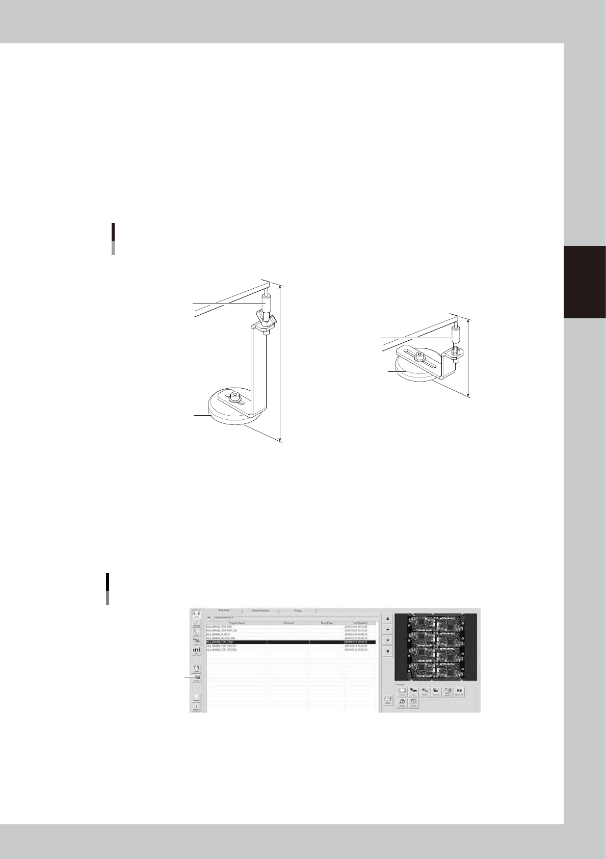
Adjust the push-up pin height.
Turn the support pins to adjust the height according to the thickness of the board to be inspected.
The push-up pin height of the single lane may vary from that of the dual lane.
• Support pin height for single lane : 140 mm – board thickness
• Support pin height for dual lane : 76 mm – board thickness
Push-up pin
Height adjustment
76 mm
140 mm
Support pin
Board
Magnet stand
Support pin
■ For single lane
■ For dual lane
Board
Magnet stand
23302-M9-00
4
Close the safety cover and reset the state of emergency stop.
Close the safety cover, cancel the emergency stop state, and press the [READY] button.
5
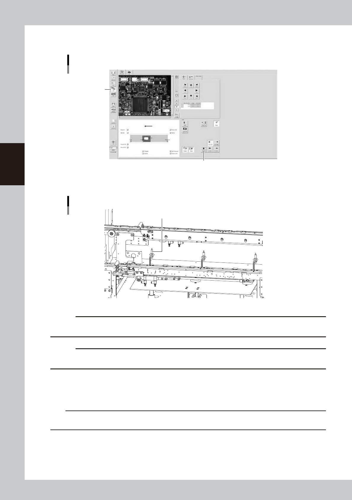
Select the board.
Select the board to be inspected.
6
Place a board at the inspection position.
Press the [Change] button and then place a board at the entrance of the conveyor.
[Change] button
[Change] button
24302-M9-10
e
7
Open the safety cover.
After making sure the board is clamped, press the emergency stop button and then open the safety
cover.
3-6
3
Daily operation
8
Arrange the push-up pins.
1. Press the [Unit] button in the button area, and press the [Push Up] button to lower the push-up plate.
[Push Up] button
[Push Up] button
[Unit] button
24303-M9-00
2. Arrange the push-up pins by taking the board size or mounting component positions into
consideration.
Arranging the push-up pins
Push-up pins
23303-M9-00
c
CAUTION
Be sure to lay out the push-up pins in a manner that they do not come into contact with the conveyor rails or other
components when the push-up plate is raised.
c
CAUTION
If the height of parts on the bottom of the board exceeds 30mm, do not use the push-up pin. Otherwise, the push-up
pin may interfere with a part.
9
Check that the board is uniformly clamped on the conveyor.
1. Press the [Push Up] button to raise the push-up plate.
2. Lightly press on the board by hand to check that there is no warp or play.
n
NOTE
If the tip of a push-up pin does not reach the backside of the board or pushes up the board too much, the push-up
pin height must be readjusted.
0
Unload the board.
1. Close the safety cover and reset the state of emergency stop.
2. Press the [Change] button to unload the board.

Chapter 4 Maintenance
Contents
Before beginning work 4-1
1. Maintaining YSi-V performance 4-2
1.1 Essential conditions and working environment 4-2
1.2 Importance of periodic inspections and cleaning 4-3
1.3 Importance of appropriate humidity management 4-3
2. Maintenance list 4-4
3. Preparing for maintenance tasks 4-6
3.1 Consumable parts 4-6
3.2 Maintenance tools 4-7
3.2.1 Cleaning tools 4-7
3.2.2 Lubricating tools and grease 4-8
3.3 Required tools 4-9
4. Weekly inspection 4-10
4.1 Checking the board sensor condition 4-10
4.2 Checking the board clamp condition 4-10
5. Monthly 4-11
5.1 Inspecting each axis 4-11
5.2 Cleaning and greasing the ball screws and linear guides 4-12
5.2.1 Cleaning and greasing the X axis ball screws 4-12
5.2.2 Cleaning and lubricating the X axis guides 4-13
5.2.3 Cleaning and greasing the Y axis ball screws 4-14
5.2.4 Cleaning and greasing the Y axes guides 4-16
5.3 Cleaning the camera lighting unit 4-17
6. Three-month inspection 4-18
6.1 Air intake fan filter 4-18
6.2 Cleaning and greasing the CZ axis (option) ball screws 4-19
7. Six-month inspection 4-20
7.1 Cleaning and greasing the marking unit (option) cam 4-20
7.2 Cleaning controller filter (For Type HS2 only) 4-21