YSi-V_Ope_E.pdf - 第74页
4-10 4 Maintenance 4. W eekly inspection 4.1 Checking the board sensor condition T his equipment uses transmission type fiber sensors as the board sensors. P eriodically chec k that these sensors correctly operate even w…
4-9
4
Maintenance
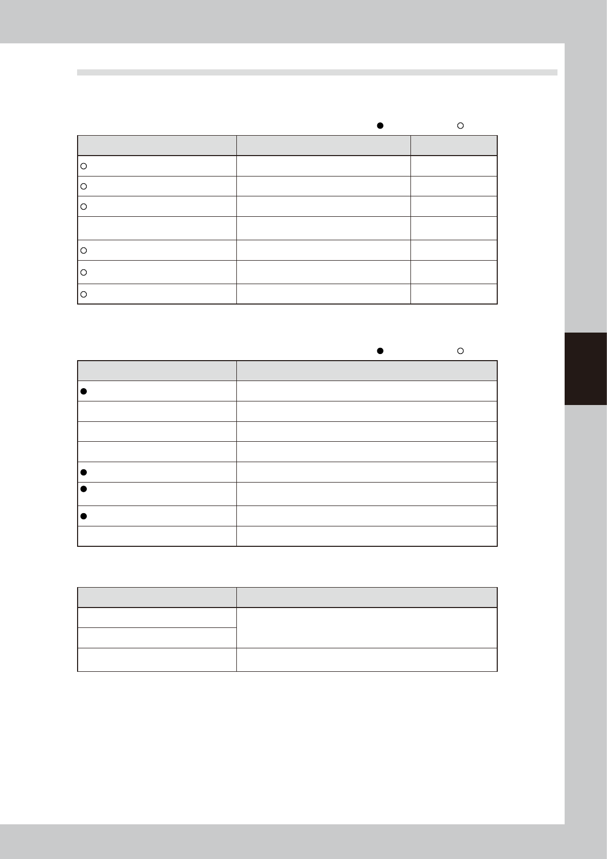
3.3 Required tools
Prepare the following tools and items necessary for maintenance.
n
Tool list
: Supplied with YSi-V, : Options
Name Description Remarks
Phillips screwdriver Large, small D-2
Slotted (flat-blade) screwdriver Large, small
Hex wrench set 1 set HEX, WRENCH SET
Tweezers
Used to remove foreign objects or debris falling
on ball screw or guide.
Grease gun Used to supply grease
Vacuum ASSY
Used to clean belt groove and sensor detection
surface.
Air blow tool Used for cleaning
n
Other tool list
: Supplied with YSi-V, : Options
Name Description
Grease (lithium-based grease: NSL) Used to lubricate each axis.
Cleaning cloth Used to clean filter cup.
Cleaning wipe Use lint-free cleaning wipe (for clean room).
Square bandage Used to prevent parts from being lost or contaminated. (2 sheets)
Cotton swab stick Used to clean camera lens, half mirror and lighting unit.
Lens cleaner,
Cleaning paper
Used to clean camera lens and lighting unit.
Lens blower brush Used to clean camera lens and lighting unit.
Fine brush (tooth brush, etc.) Used to clean the belt groove, etc.
n
Safety goggles and mask
Name Description
Dust-proof goggles
Always wear these goggles and mask when applying grease or when
using an air blow tool.
Dust-proof mask
Protective gloves
Always wear protective gloves when applying grease or when removing
optical camera cover.
4-10
4
Maintenance
4. Weekly inspection
4.1 Checking the board sensor condition
This equipment uses transmission type fiber sensors as the board sensors. Periodically check that these sensors
correctly operate even when the conveyor rail width is changed.
1
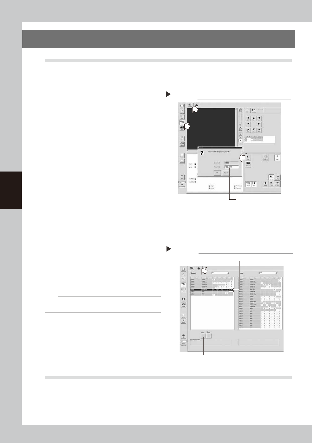
Open the [Unit] – [Conveyor] tab.
2
Press the [Width] button to change
the conveyor width.
1. When the “Conveyor” dialog box
appears, enter the maximum conveyor
width in the "Target Width" box and press
the [OK] button. The conveyor width will
automatically change to the specified
size.
2. Then, enter the minimum conveyor width
(50mm) in the “Target Width” box and
press the [OK] button. The conveyor
width will automatically change to the
specified size.
54400-M9-10
3
Check whether an error has
occurred.
The conveyor sensor is operating properly
unless an error message appears when the
conveyor width is changed. No further
check is necessary.
If an error message appears, follow the steps
below to adjust the sensor.
n
Adjusting the conveyor sensor
If an error occurred when the conveyor width was
changed, perform the auto-tuning of the conveyor
sensor.
1. Open the [Unit] – [I/O] tab.
2. In the Output list, select “CONVEYOR” (T01000E0).
n
NOTE
For the dual lane specifications, (T01000E0) corresponds
to lane 1 while (T01000E2) corresponds to lane 2.
3. Press the [ON/OFF] button to change to 0 (OFF)
→
1 (ON)
→
0 (OFF) and perform the auto-tuning.
4. Press the [Width] button again to change the
conveyor width in the same manner as described in
Step2. When no error message appears, the sensor
operates correctly.
54401-M9-10
4.2 Checking the board clamp condition
Check the following points when a board is clamped on the conveyor.
1. Check that the board is securely clamped and there is no play.
2. Check that there is no clearance between the board hold plate and the board.
3. Check that the board surface is flush with the conveyor rail upper surface.
4. Check that the board clamp unit moves smoothly.
Changing the conveyor width
Enter the conveyor width here.
Step 2
Tuning conveyor sensor
3
2

4-11
4
Maintenance
5. Monthly
5.1 Inspecting each axis
Inspect the ball screws and the guides on each axis.
Check the following points.
n
NOTE
A grease spattering prevention cover is attached along each axis. Remove the cover before inspection and reattach
it in place after inspection.
Checkpoints
1. Any foreign matter or chips adhering to the ball screws and linear guides?
2. Do the ball screws and linear guides have the correct amount of grease?
Check if grease has flowed off or splattered in the air failing to adhere. Also check if grease has discolored or
hardened.
3. Any abnormal sounds from the ball screws?
Press the emergency stop button. Then check for any abnormal sounds while pushing the unit by hand along the X-axis
or Y-axis back and forth.
Countermeasures
1. Ball screws and linear guides may be damaged when chips or debris bite into them. If chips or debris are adhering,
wipe them off along with the grease or remove with tweezers, etc.
2. Apply grease while referring to "Cleaning and greasing the ball screws and linear guides of each axis" described later.
3. Consult your YAMAHA sales office or representative when abnormal sounds occur even after trying the
countermeasures in the above steps 1 and 2.
c
CAUTIN
• When handling grease or lubricant, read and follow the precautions listed in section "3.2.2 Lubricating tools and
grease", in this chapter.
• If abnormal noise is emitted from the ball screw or guide of each axis, then contact our sales representative for
assistance. Disassembly and cleaning of the ball screw or guide by the user will void the warranty.