Operating Instructions_VF366_en.pdf - 第407页
9|Spare and wear parts Single solder pot positioning system, view [X], [Y] 1 3 2 4 5 Fig.162: EM113-20-00Ab Pos Description Item number A B 1 Adjusting screw 135733 x 2 Energy chain 188761 x 3 Tooth belt 25AT10 L = 26…
9|Spare and wear parts
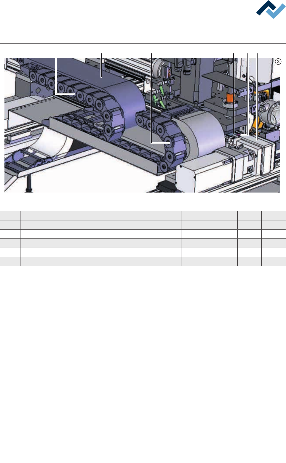
Single solder pot positioning system, view [X]
1 1 52 3 4
Fig.161: EM113-20-00Aa
Pos Description Item number A B
1 Energy chain 188754 x
2 Energy chain 188750 x
4 Tooth belt 25AT10 L = 2840 mm 216461 x
5 Wearing part package steel band deflection 175815 x
6 Blanket for positioning system: EM113-20-00A (not shown) 253569 x
Ersa GmbH Operating Instructions_VF366_en|Rev. 14|30/11/2017 406/551
9|Spare and wear parts
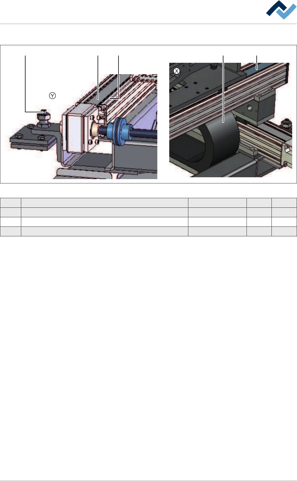
Single solder pot positioning system, view [X], [Y]
1 3 24 5
Fig.162: EM113-20-00Ab
Pos Description Item number A B
1 Adjusting screw 135733 x
2 Energy chain 188761 x
3 Tooth belt 25AT10 L = 2600 mm 216462 x
Ersa GmbH Operating Instructions_VF366_en|Rev. 14|30/11/2017 407/551
9|Spare and wear parts
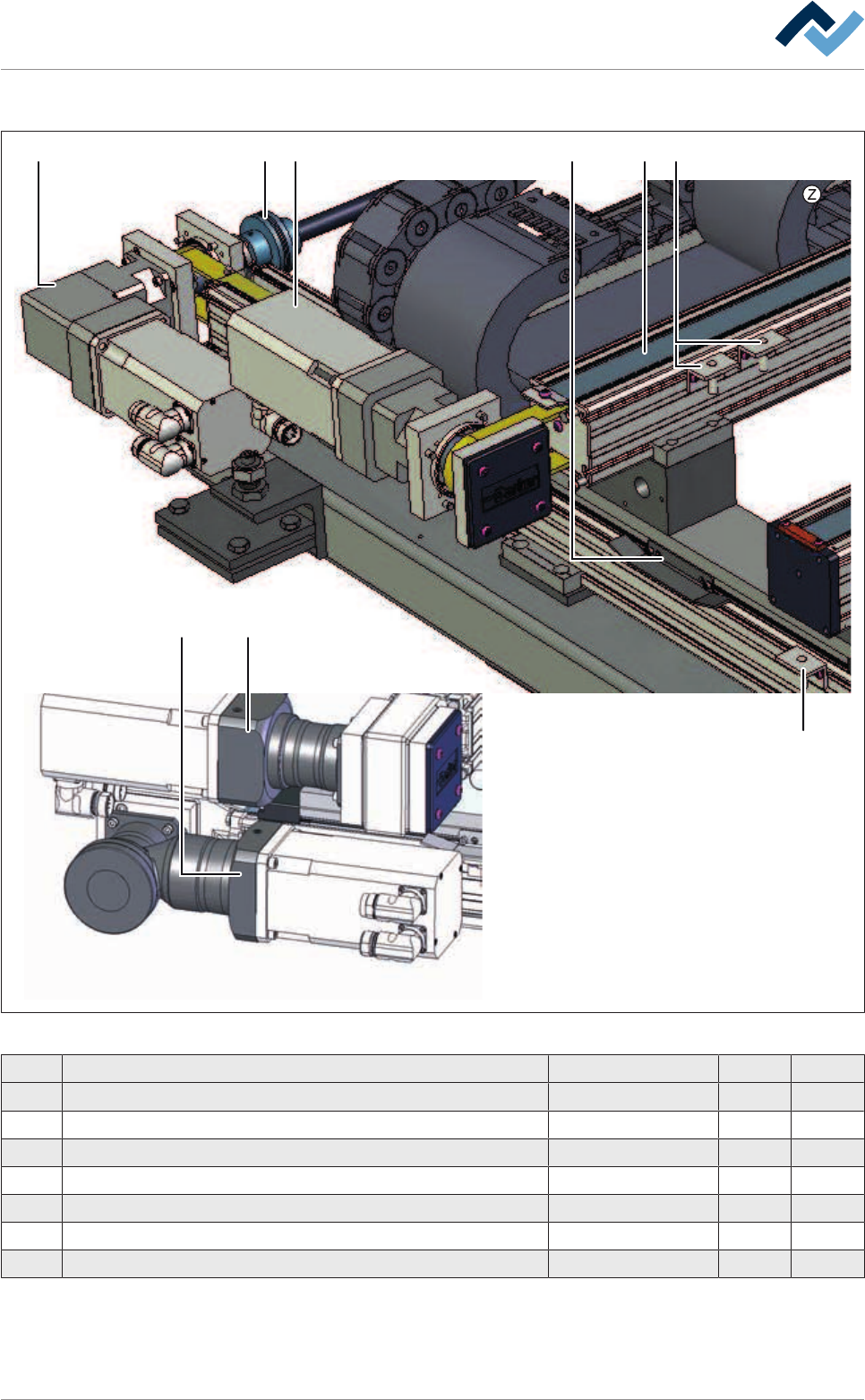
Single solder pot positioning system, view [Z]
1
1
3
3
4 22
2
5
Fig.163: EM113-20-00Ac
Pos Description Item number A B
1 Motor/gear combination --> 2010 175816 x
1 Motor/gear combination 2010 --> 191607 x
2 Motor/gear combination --> 2010 175817 x
2 Motor/gear combination 2010 --> 191608 x
3 Assembly set limit switch 175818 x
4 Cam set 175819 x
5 Coupling 175820 x
Ersa GmbH Operating Instructions_VF366_en|Rev. 14|30/11/2017 408/551