Operating Instructions_VF366_en.pdf - 第415页
9|Spare and wear parts Double solder pot positioning system, view [W] 1 Fig.168: EM113-24-00c Pos Description Item number A B 1 Energy chain 188761 x Ersa GmbH Operating Instructions_VF366_en|Rev. 14|30/11/2017 41…
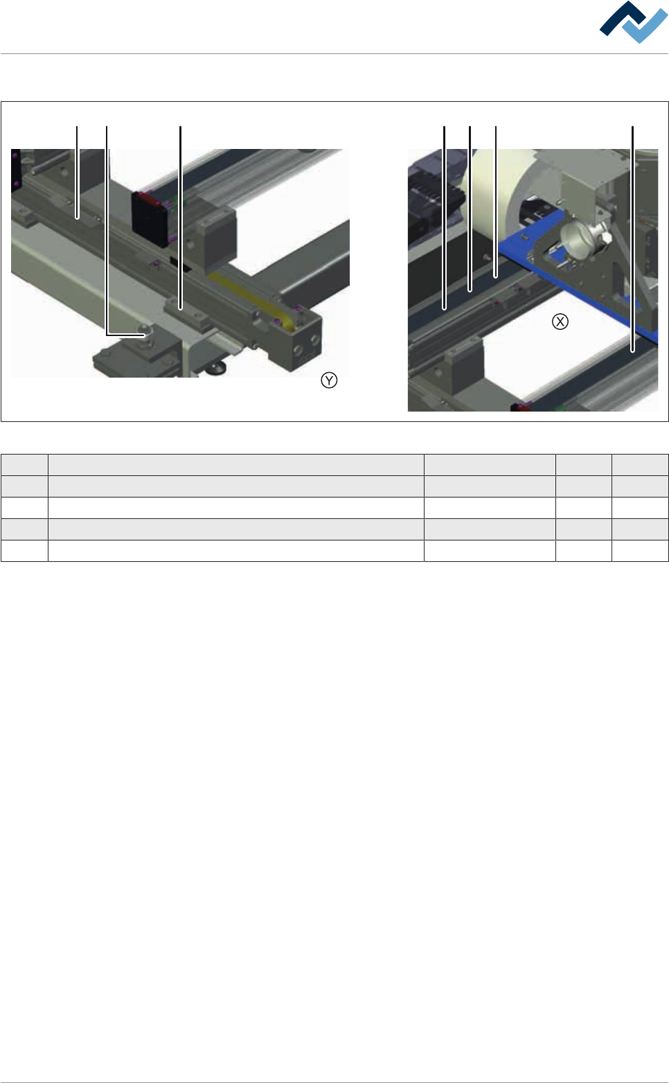
9|Spare and wear parts
Double solder pot positioning system, view [X], [Y]
24576 31
Fig.167: EM113-24-00b
Pos Description Item number A B
4 Wearing part package steel band deflection 175815 x
5 Assembly set limit switch 175818 x
6 Cam set 175819 x
7 Adjusting screw 135733 x
Ersa GmbH Operating Instructions_VF366_en|Rev. 14|30/11/2017 414/551
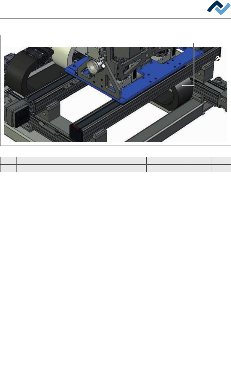
9|Spare and wear parts
Double solder pot positioning system, view [W]
1
Fig.168: EM113-24-00c
Pos Description Item number A B
1 Energy chain 188761 x
Ersa GmbH Operating Instructions_VF366_en|Rev. 14|30/11/2017 415/551
9|Spare and wear parts
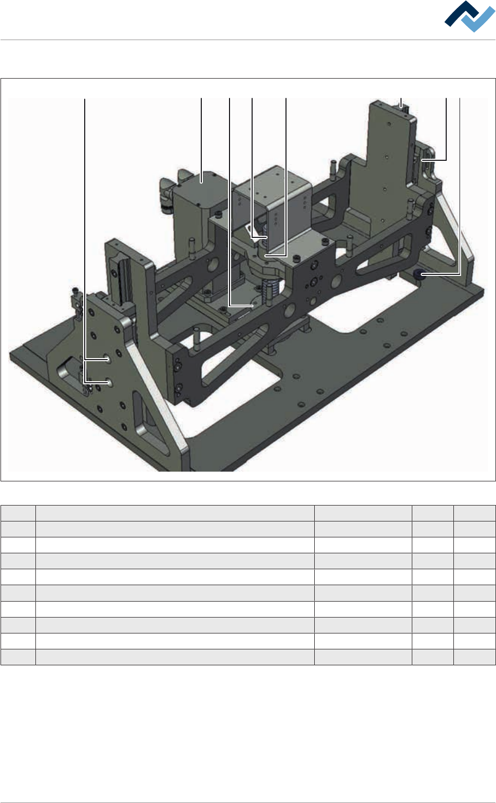
9.4.4 Z-axis double pot (dual track)
21 738 5 64
Fig.169: EM113-29-01-00
Pos Designation Item number A B
1 Guide rail, L = 308 mm 142681 x
2 Guide wagon 149199 x
3 Solid mounting 114287 x
4 Servo drive with resolver 23567 x
5 Lifting spindle, complete, 25 x 5 * 142731 x
6 Ball nut * 155072 x
7 Rubber bumper 121899 x
8 Grease nipple, 90° 6SCHMNI6X1-90 x
* Only deliverable together
Ersa GmbH Operating Instructions_VF366_en|Rev. 14|30/11/2017 416/551