00198788-01_UM_SSI_DE_EN.pdf - 第41页
3 Function description and structure 3.1 Function description User Manual / Bedienungsanleitung SIPLACE Single Slot Interface 05/2021 41 3 Function description and structure 3.1 Function description Purpose and structure…
2 Operational safety
2.1 Safety Instructions
40 User Manual / Bedienungsanleitung SIPLACE Single Slot Interface 05/2021
2.1.3 Important notes on operational safety
The following points must be observed in order to maintain operational safety:
2.1.3.1 General
► Operational safety is only guaranteed during use of the user guide as prescribed.
► Always observe the applicable accident prevention regulations and the special safety regula-
tions in your country.
► If it is necessary to work on the machine and you do not have adequately trained personnel
within your operation, always call in a ASM Assembly Systems GmbH & Co. KG service en-
gineer! ASM Assembly Systems GmbH & Co. KG will not accept liability for any damage or
consequential damage that is the result of incorrect work!
► If particularly hazardous situations are identified while the module is in use, the module owner
must immediately notify the manufacturer in writing so that appropriate action can be taken to
reduce the potential danger.
WARNING
Safe operation of module
In spite of all the safety precautions taken by the manufacturer, failure to use the module as
prescribed can result in severe physical injury and/or considerable damage to equipment!
For the module to be safe, it must be used correctly by qualified personnel and all warnings
must be observed! Some work requires training that goes beyond the scope of this manual.
2.1.3.2 Safety of Operators and Other Persons
► Module operators may only carry out work for which they have been adequately trained and
with which they are totally familiar!
► NEVER open any of the covers if you are not totally familiar with the use and functioning of
the module! Do not open the covers during operation unless you are told to do so in this
manual or in the station software dialog!
► For your own safety, wear work clothes that conform to the guidelines of the professional
association, i.e. no wide sleeves etc.
► Reduce the risks by not wearing scarves, chains or ties at your work post.
► People with long hair must wear a protective head covering.
WARNING
Voltage
The module is electrically driven. When electrical devices are in use, certain parts carry
dangerous voltage levels!
► When performing work on parts conducting electricity, disconnect the power pack from
the power supply by unplugging the mains plug.
ð There is a risk of death, severe injury and/or considerable damage to equipment if
these instructions are not followed!
2.1.3.3 Safety of Plant and Equipment
► Never make changes, however minor, unless you are totally aware of the effect they will have
on the overall functioning of the module and system!
► The modules must always be set up, retooled and maintained by appropriately trained person-
nel.
► Do not make modifications to the safety equipment. In particular, NEVER deactivate circuit-
breakers or remove safety devices.

3 Function description and structure
3.1 Function description
User Manual / Bedienungsanleitung SIPLACE Single Slot Interface 05/2021 41
3 Function description and structure
3.1 Function description
Purpose and structure
The Single Slot Interface (referred to as SSI in this document) enables you to operate X feeder
modules outside a placement machine or a pre-setup area. The SSI consists of a steel frame,
which accommodates the X feeder module. Inside, electronics provide the voltage supply and com-
munication functions.
Areas of application
The SSI is designed for the inspecting, servicing and repairing of feeder modules. It can also be
used for the pre-setup function in PCB production. A component tape can be inserted into a single
feeder module and settings such as clock rate, pickup position and speed can be defined.
EDIF
The X feeder modules are equipped with an EDIF. EDIF stands for Energy and Data Interface. The
X feeder modules use a non-contact system for the electrical transmission of energy and commu-
nication of data. This enables you to place the feeder modules on the component table or SSI and
to remove them from the table, without the need to connect/disconnect cables.
3 Function description and structure
3.2 Structure
42 User Manual / Bedienungsanleitung SIPLACE Single Slot Interface 05/2021
3.2 Structure
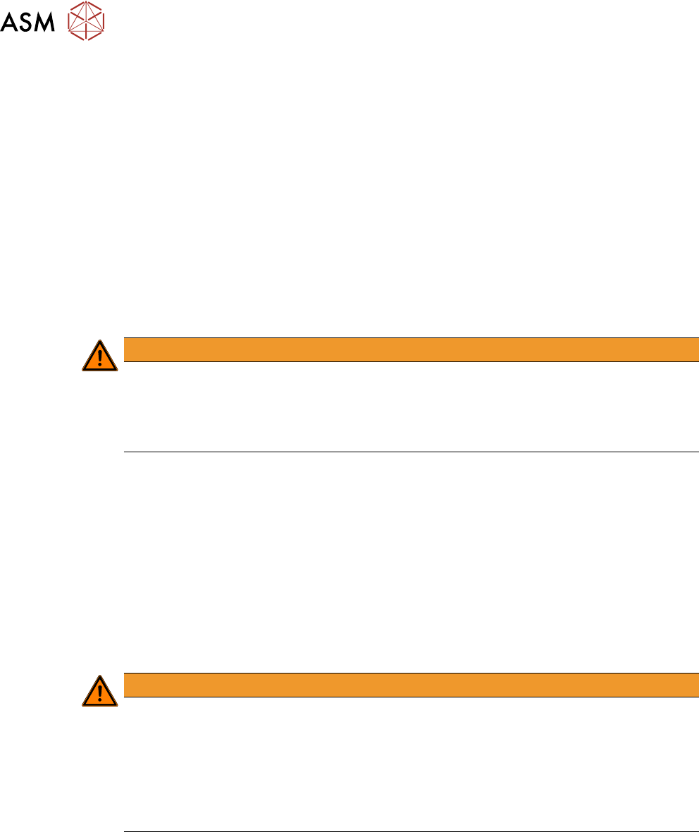
Interfaces
The SSI provides the voltage supply for the feeder module. It also has a CAN bus interface. This
enables data to be exported from the feeder module or data/commands to be sent to the feeder
module. Up to four SSIs can be connected via a CAN bus cable to a CIN box.
NOTICE
Enabling the terminating resistor
The terminating resistors need to be activated at the beginning and end of the bus system.
The terminating resistors at all other nodes in the bus system must be deactivated.
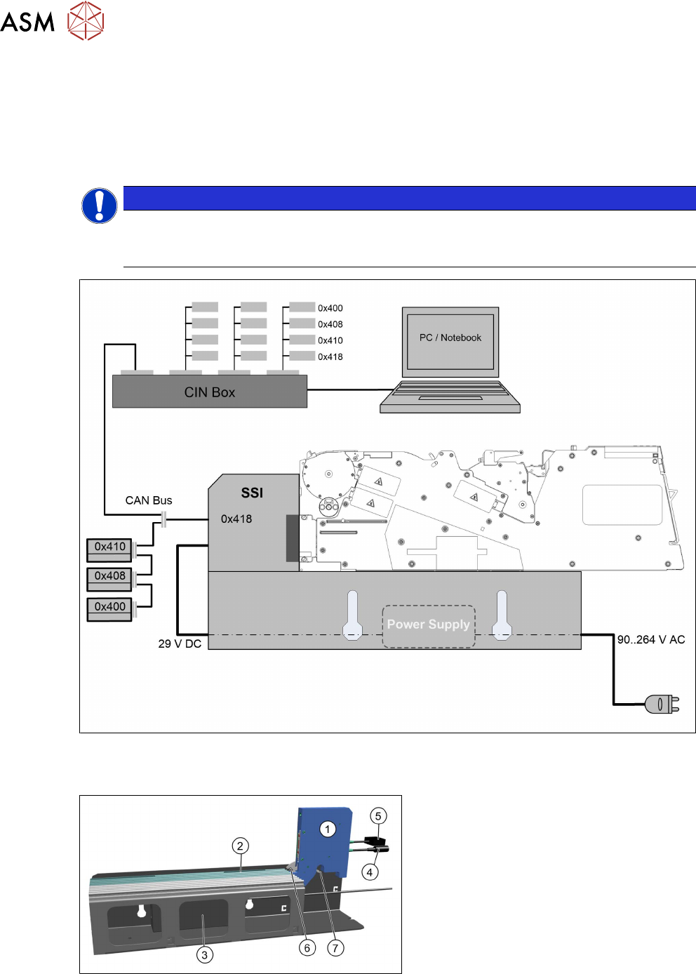
Fig.1: SSI interface
SSI parts
(1) Energy and data interface (EDIF)
(2) Omega rail
(3) Power pack
(4) Connection cable for voltage supply
(5) Connection cable for data transfer
(6) Locking hook for feeder module
(7) Locking latch for releasing the locking
mechanism