00198788-01_UM_SSI_DE_EN.pdf - 第58页
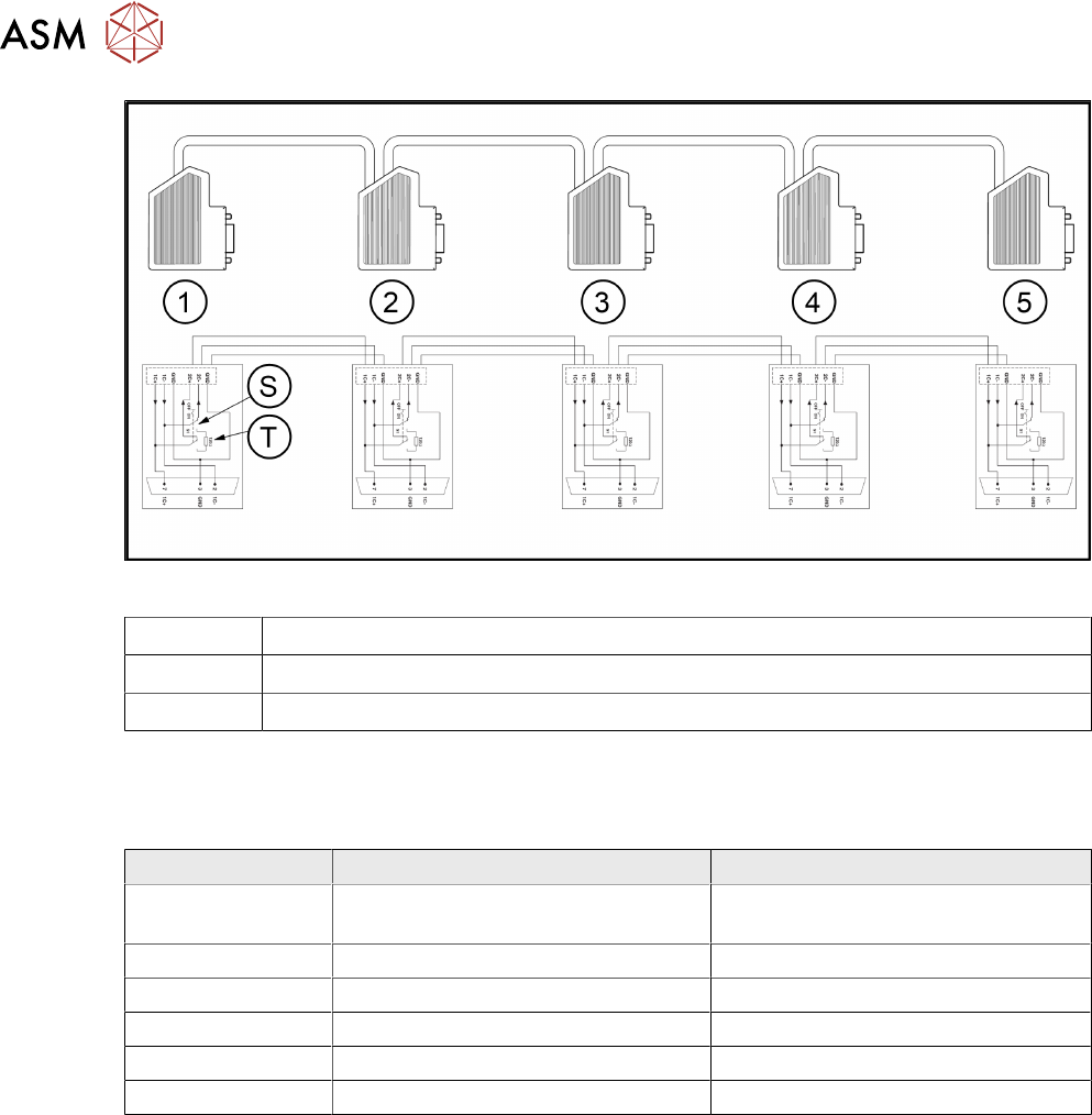
6 Overviews 6.3 Spare Parts 58 User Manual / Bedienungsanleitung SIPLACE Single Slot Interface 05/2021 Fig.5: CAN bus cable circuit diagram 1 - 5 Connector 1 to 5 on the bus cable S Sliding switch on the connector T Ter…
6 Overviews
6.1 Block diagram of power pack and EDIF
User Manual / Bedienungsanleitung SIPLACE Single Slot Interface 05/2021 57
6 Overviews
6.1 Block diagram of power pack and EDIF
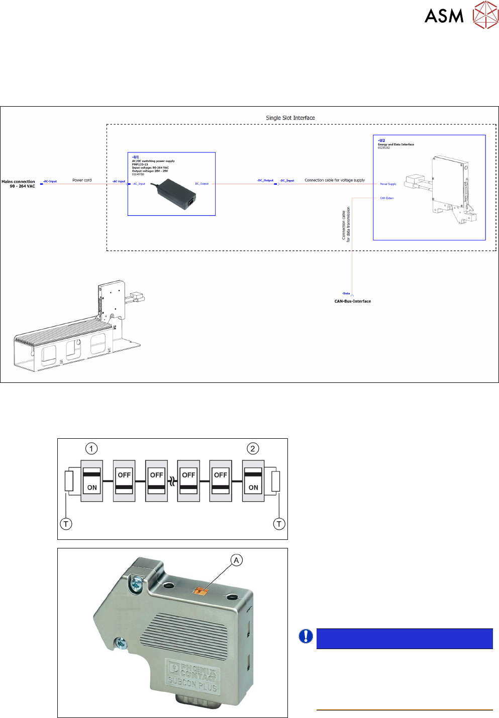
Fig.4: Block diagram of power pack and EDIF
6.2 CAN bus cable, docking station, terminating resistor
The terminating resistors (T)are activated at
the beginning (1)
and end (2) of the bus sys-
tem. At the same time, the cable connection
terminals (2C+/2C-) for the continuing bus
cable are switched off.
► Push the sliding switch (A) on the SUB-
D connector at the beginning of the bus
system to ON.
► Push the sliding switch (A) on the SUB-
D connector at the end of the bus sys-
tem to ON.
NOTICE!
The terminating resistors at all
other nodes in the bus system must
be deactivated! The sliding switch
for the relevant SUB-D connector
must be set to OFF.
.
6 Overviews
6.3 Spare Parts
58 User Manual / Bedienungsanleitung SIPLACE Single Slot Interface 05/2021
Fig.5: CAN bus cable circuit diagram
1 - 5 Connector 1 to 5 on the bus cable
S Sliding switch on the connector
T Terminating resistor on the switch
6.3 Spare Parts
The following spare parts are available for the SSI:
Item number Term in German Term in English
03149780-xx Power supply 90-264VAC 135W 29V
4.8A assy.
Power supply 90-264VAC 135W 29V
4.8A assy.
03127274-xx PCBA Single Slot EDIF 2 * PCBA Single Slot EDIF 2
03110865-xx PCBA Single Slot EDIF IrDA-Board II PCBA Single Slot EDIF IrDA board II
03042155-xx Energie-Dateninterface assy. SSI Energy data interface assembly SSI
03048718-xx Kabel für SSI Power Cable for SSI power
03048719-xx Kabel für SSI Daten Cable for SSI data
* FBG = Flach Bau Gruppe = Platine, elektrische Schaltung (English = PCB = Printed Circuit
B
oard)