00198788-01_UM_SSI_DE_EN.pdf - 第50页
4 Operation 4.5 Preparation table 50 User Manual / Bedienungsanleitung SIPLACE Single Slot Interface 05/2021 ► Position the SSI between the guide profiles and push it towards the back knurled screw until half the drilled…
4 Operation
4.4 Table adapter
User Manual / Bedienungsanleitung SIPLACE Single Slot Interface 05/2021 49
4.4 Table adapter
If you want to use the SSI for pre-setup, it can be fitted to a table adapter. This increases the stabil-
ity of the equipment and give the component reel a fixed place.
WARNING
Injury from falling parts
The assembly must be correctly placed on the table to prevent it falling down and causing
any injuries.
Sales number: 00120672-xx
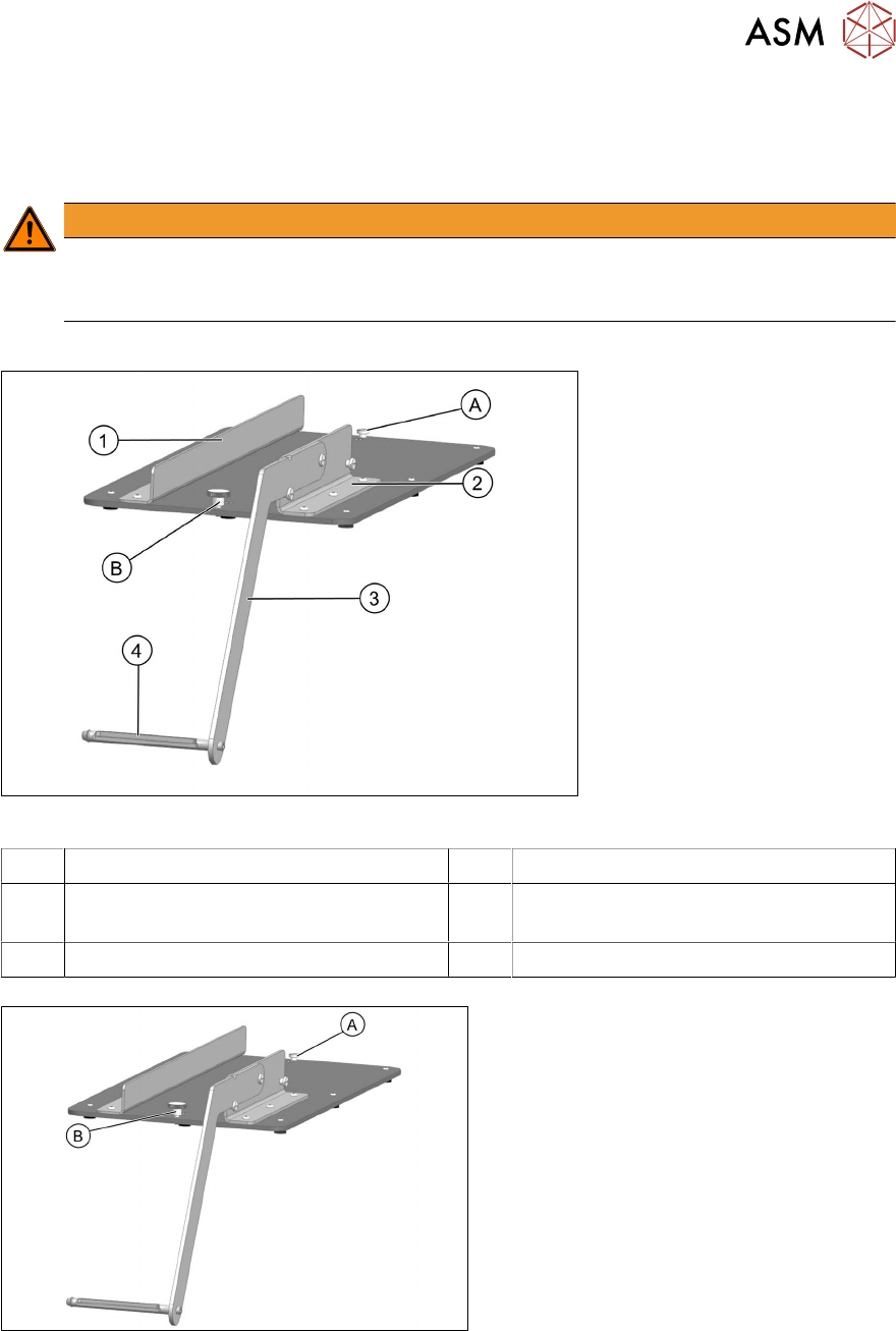
Fig.2: SSI table adapter
1 Führungsprofil links 2 Guide profile, right
3 Reel arm 4 Axis for accommodating the component
reel
A Knurled screw, back B Knurled screw, front
Fasten the SSI to the table adapter:
► Loosen the back knurled screw (A) until
it is only slightly in the base plate.
► Loosen the front knurled screw (B)
completely.
4 Operation
4.5 Preparation table
50 User Manual / Bedienungsanleitung SIPLACE Single Slot Interface 05/2021
► Position the SSI between the guide
profiles and push it towards the back
knurled screw until half the drilled hole
(A)
on the SSI frame profile is against
the knurled screw.
► Tighten the knurled screw.
► Insert the other knurled screw through
the front drilled hole (B)
in the frame
profile and into the hole drilled in the
table adapter.
► Tighten the knurled screw.
4.5 Preparation table
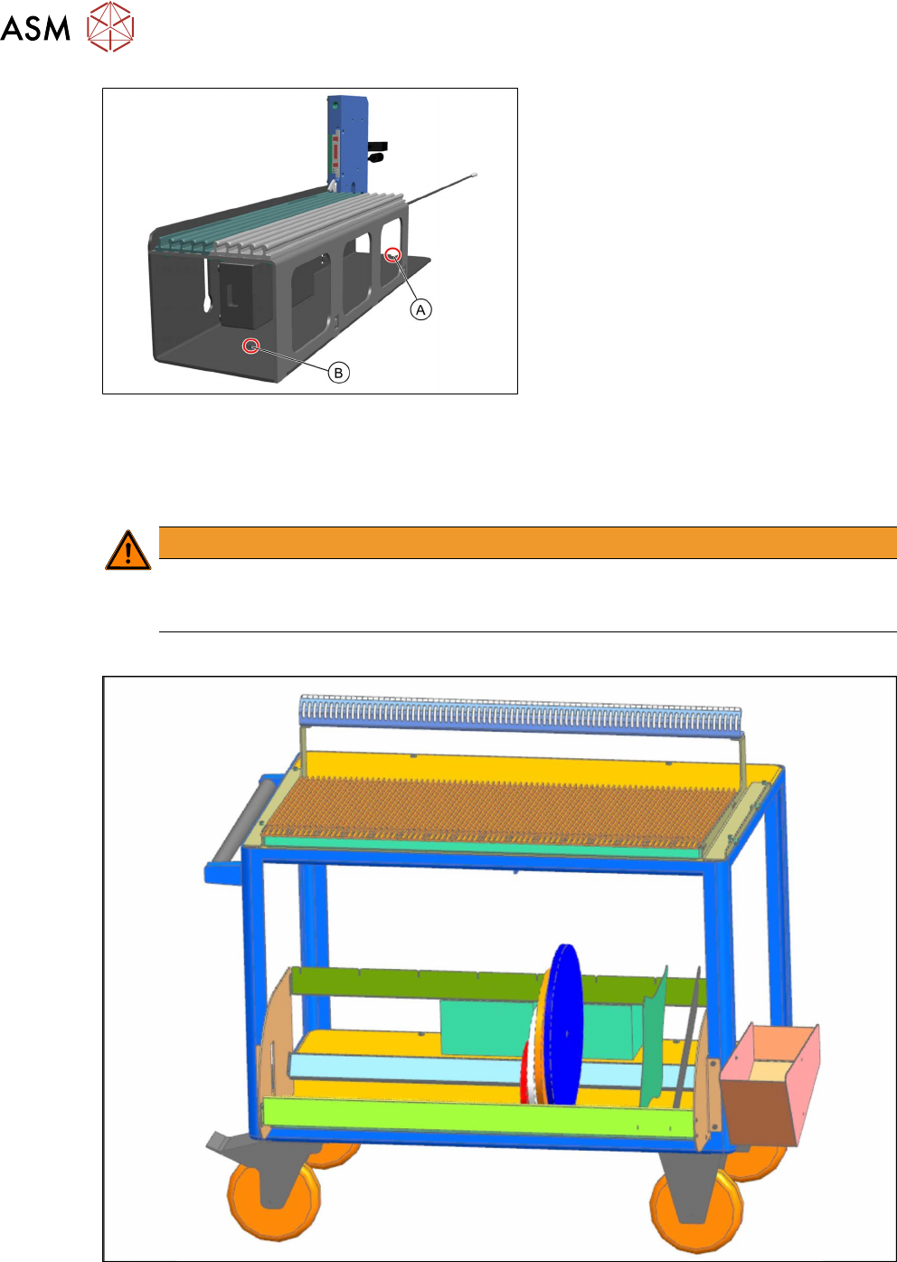
Multiple feeder modules can be set up (pre-setup) on one preparation table at the same time. At
the same time, an SSI can be fitted to the side of the preparation table.
WARNING
Injury from falling parts
The assembly must be correctly placed on the preparation table to prevent it falling down
and causing any injuries.
Sales number: 00120670-xx
Fig.3: Preparation table
4 Operation
4.6 Tasks for Setup Center
User Manual / Bedienungsanleitung SIPLACE Single Slot Interface 05/2021 51
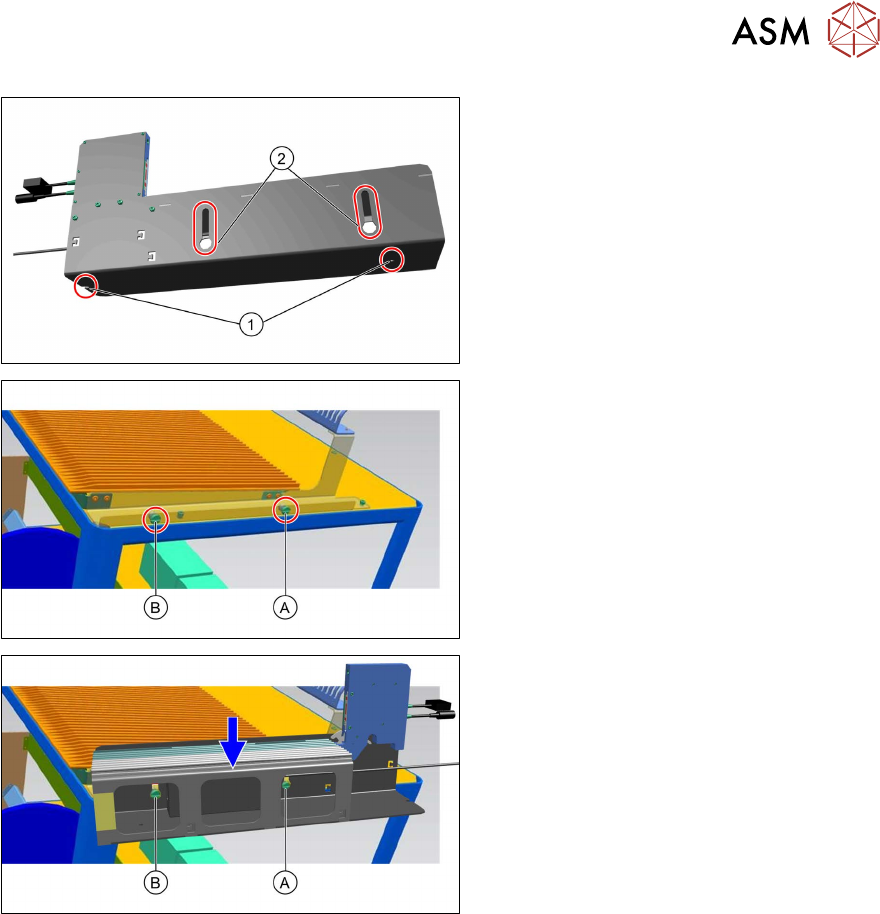
Assembly on a preparation table:
► When assembling on the preparation
table, use the hook-up slots (2)
on the
left side of the SSI steel frame.
► The right side of the preparation table
has slotted screws (A)
and (B) for
hooking up the SSI.
► Guide the hook-up slots on the steel
frame over the slotted screws (A)
and
(B)
and press the steel frame down-
wards.
4.6 Tasks for Setup Center
Configuring the SSI in Setup Center
In the main menu, select Extras -> Settings and then select the category Single Slot Interfaces
to configure the Single Slot Interfaces:
●
Add SSI
●
Removing the selected SSI
●
Editing the selected SSI
●
List of SSIs present
●
Updating information about a connected SSI
For details see the user manual "ASM Setup Center 9.8", section "Single Slot Configuring Setup
Center".