00198788-01_UM_SSI_DE_EN.pdf - 第42页
3 Function description and structure 3.2 Structure 42 User Manual / Bedienungsanleitung SIPLACE Single Slot Interface 05/2021 3.2 Structure Interfaces The SSI provides the voltage supply for the feeder module. It also ha…

3 Function description and structure
3.1 Function description
User Manual / Bedienungsanleitung SIPLACE Single Slot Interface 05/2021 41
3 Function description and structure
3.1 Function description
Purpose and structure
The Single Slot Interface (referred to as SSI in this document) enables you to operate X feeder
modules outside a placement machine or a pre-setup area. The SSI consists of a steel frame,
which accommodates the X feeder module. Inside, electronics provide the voltage supply and com-
munication functions.
Areas of application
The SSI is designed for the inspecting, servicing and repairing of feeder modules. It can also be
used for the pre-setup function in PCB production. A component tape can be inserted into a single
feeder module and settings such as clock rate, pickup position and speed can be defined.
EDIF
The X feeder modules are equipped with an EDIF. EDIF stands for Energy and Data Interface. The
X feeder modules use a non-contact system for the electrical transmission of energy and commu-
nication of data. This enables you to place the feeder modules on the component table or SSI and
to remove them from the table, without the need to connect/disconnect cables.
3 Function description and structure
3.2 Structure
42 User Manual / Bedienungsanleitung SIPLACE Single Slot Interface 05/2021
3.2 Structure
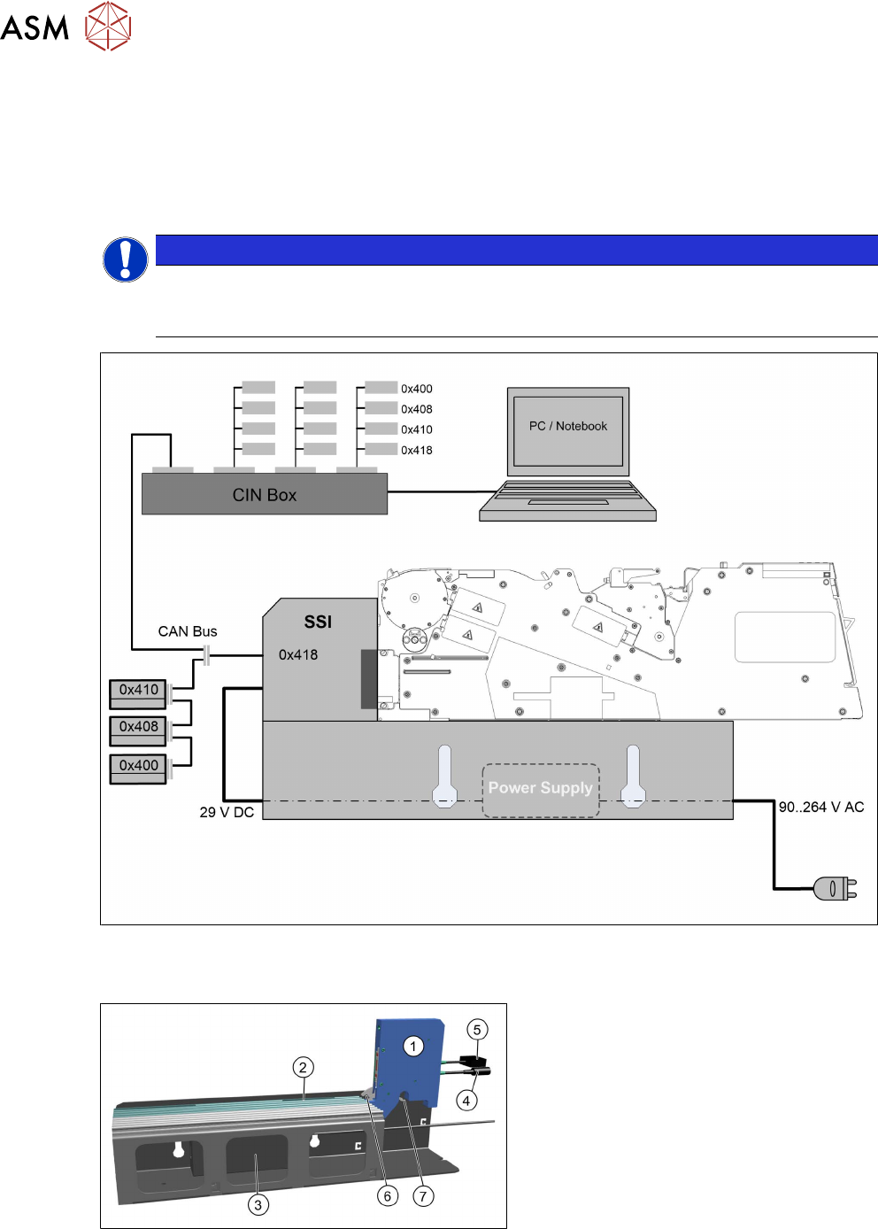
Interfaces
The SSI provides the voltage supply for the feeder module. It also has a CAN bus interface. This
enables data to be exported from the feeder module or data/commands to be sent to the feeder
module. Up to four SSIs can be connected via a CAN bus cable to a CIN box.
NOTICE
Enabling the terminating resistor
The terminating resistors need to be activated at the beginning and end of the bus system.
The terminating resistors at all other nodes in the bus system must be deactivated.
Fig.1: SSI interface
SSI parts
(1) Energy and data interface (EDIF)
(2) Omega rail
(3) Power pack
(4) Connection cable for voltage supply
(5) Connection cable for data transfer
(6) Locking hook for feeder module
(7) Locking latch for releasing the locking
mechanism
3 Function description and structure
3.3 Repairing the X Feeder Modules
User Manual / Bedienungsanleitung SIPLACE Single Slot Interface 05/2021 43
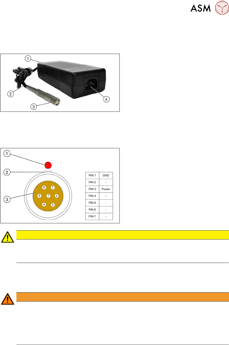
Power pack
To operate the SSI, the power pack supplied provides the required voltage of 29 V to a 7-pin Lemo
connector. The nominal voltage can be 90-264 VAC. The power pack automatically adjusts to the
incoming voltage.
The underside of the power pack is fitted
with Velcro tape to the inside of the steel
frame, so that the power on indicator (1)
is
visible.
The power pack cable (2) is run towards the
back in the steel frame and the Lemo con-
nector (3)
is connected to the SSI power
supply cable.
The connection plug (4) for the mains power
cable points towards the front of the steel
frame. The delivery package includes a Ger-
man mains cable and a US version mains
cable. Use the mains cable suitable for your
mains connection, to connect the SSI to the
power supply.
Connector on power pack cable:
(1) Red dot on the connector (identifying
mark)
(2) Groove (reverse polarity protection)
(3) Contacts (see table for assignment)
CAUTION
Operational safety
The power pack is electrically designed so that the SSI can be safely supplied with voltage.
► Only operate the SSI with this power pack.
3.3 Repairing the X Feeder Modules
If operating the feeder module when it is open with the SSI, observe the following:
WARNING
Observe the ESD regulations
Observe ESD safety regulations for the feeder modules:
► Before you open the side cover, make sure you are wearing the ESD protection wrist-
band, to prevent damage to the highly sensitive boards inside the feeder module.
► When working with the open feeder module, always use suitable ESD protection.
(ESD support, workplace, wristband)
There are no hazardous voltages in the feeder module itself. The cable and control boards only use
up to a maximum of 42 V (low voltage threshold).
Information about repairing the X feeder modules.
For more information about repairing the X feeder modules, refer to the service manual for the X
feeder modules.