00193875-01.pdf - 第16页
3 Graphical user interface SIPLA CE Software Guide Version 101.xx 3.1 Inputs and controls Issue 05/03 EN 16 3 Graphical user interface This section describes how t o use the various cont rols such as the keyboard , track…
SIPLACE Software Guide Version 101.xx 2 Introduction and basic terms
Issue 05/03 EN 2.2 Overview
15
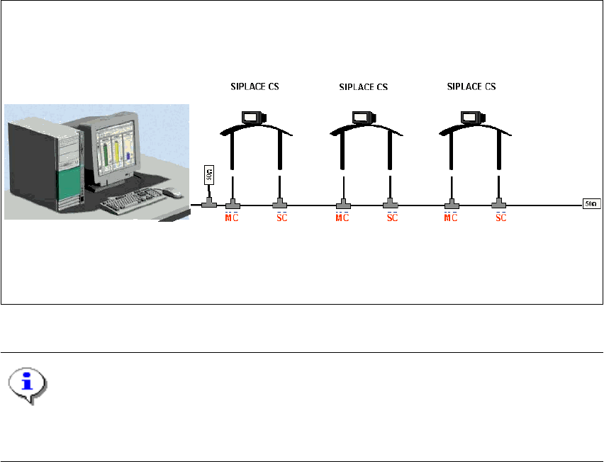
2.2.3 Overview of the system components that make up a SIPLACE line
2
The individual stations obtain their placement data from a control computer (SIPLACE C Pro). 2
2
Fig. 2.2 - 5 Schematic diagram of the network in a SIPLACE line (example)
NOTE
A line with up to 5 stations (SIPLACE CS and CF) is supported by the SIPLACE C Pro pro-
gramming system. 2
The placement data is sent by the job control facility on the host computer to the various stations.2
2
Control computer
(SIPLACE C Pro)
Line
3 Graphical user interface SIPLACE Software Guide Version 101.xx
3.1 Inputs and controls Issue 05/03 EN
16
3 Graphical user interface
This section describes how to use the various controls such as the keyboard, trackball and mouse
buttons and also introduces the functions of the individual components of the graphical user inter-
face. 3
WARNING
In addition, the safety notes of the User Manual for SIPLACE CS/CF take priority. 3
3.1 Inputs and controls
Keyboard 3
The keyboard with its integrated trackball and mouse buttons acts as the standard input tool for
the graphical user interface of the station computer software. 3
Trackball and mouse buttons 3
You use the trackball to move the mouse pointer across the user interface to the desired object
and then use the left mouse button to select the object or execute the appropriate function. 3
NOTE
In this guide, triggering an action using the left mouse button is always referred to as "clicking".3
3
SIPLACE Software Guide Version 101.xx 3 Graphical user interface
Issue 05/03 EN 3.2 Components of the user interface
17
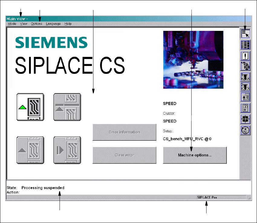
3.2 Components of the user interface
3
Fig. 3.2 - 1 Components of the user interface (for example, the Main view of the CS)
3
Key to Fig. 3.2 - 1
(1) Title bar
(2) Menu bar
(3) Working area/display area
(4) Controls
(5) Toolbar
(6) Status area
(7) Info bar
1
6
7
5
2
3
4