00193875-01.pdf - 第28页
3 Graphical user interface SIPLA CE Software Guide Version 101.xx 3.3 User interface - views and menus Issue 05/03 EN 28 Shut down computer... 3 All applications are closed wit hout any files whi ch may have been process…
SIPLACE Software Guide Version 101.xx 3 Graphical user interface
Issue 05/03 EN 3.3 User interface - views and menus
27
Start OIS 3
This menu function starts the software for the "Operator Information System". The production data
acquisition system can be used to obtain information about the operating behavior of a complete
line or an individual station. 3
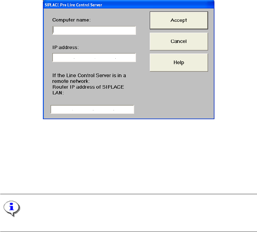
Configure SIPLACE Pro connection... 3
In this dialog box, you can specify which computer is permitted to provide the current station com-
puter with data: 3
3
Fig. 3.3 - 1 SIPLACE Pro Line Control Server
3
Switch to operating system... 3
You use this menu item to switch to the Windows operating system after entering your password.
From here, you can then subsequently return to the SIPLACE user interface. 3
NOTE
This menu option is not available at the "Operator" access level. 3
Æ Click the Switch to operating system... menu item.
This shows the Windows user interface. The station computer software continues to run in the
background.
3
3 Graphical user interface SIPLACE Software Guide Version 101.xx
3.3 User interface - views and menus Issue 05/03 EN
28
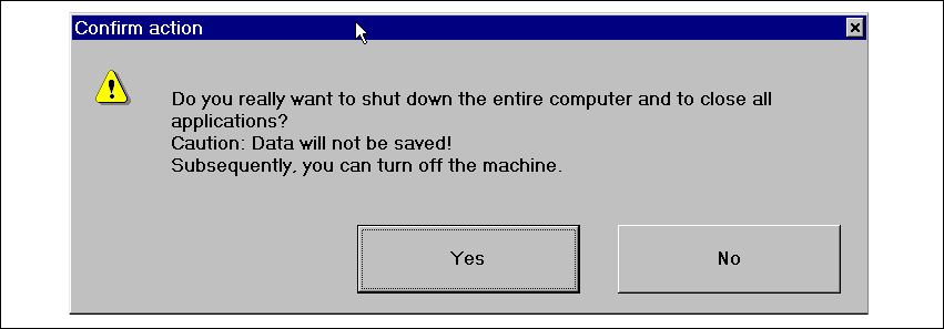
Shut down computer... 3
All applications are closed without any files which may have been processed being saved and the
station computer is shut down. 3
Æ Click the Shut down computer... menu item.
The following dialog box will be opened.
3
Fig. 3.3 - 2 " Shut down computer" dialog box
Æ Click Yes if you want to terminate your work.
The station computer is shut down.
Æ Wait until the computer has shut down completely, and then switch off the station at the main
switch.
3
3

SIPLACE Software Guide Version 101.xx 3 Graphical user interface
Issue 05/03 EN 3.3 User interface - views and menus
29
3.3.2.2 "View" menu"
The "View" menu contains the options for calling the placement functions, single functions and vi-
sion functions. It is also used to start the SITEST test program. 3
Æ Click the required menu option.
The screen display is switched to the corresponding view. From there you can carry out the
required functions.
NOTE
All the options in this menu can also be called by clicking the corresponding toolbar button (see
section 3.2.2) or by pressing the corresponding function key. If shortcuts have been defined, these
can also be used. 3
NOTE
The 3 menu options below belong to the group of placement functions. 3
Set-up F2 3
The setup for a feeder location is displayed in tabular form. It can be called separately for each of
the max. four locations. 3
Error F3 3
Errors are differentiated by type and each error type is presented in a separate table. You can call
separate tables for track errors, conveyor errors, machine errors and general errors.
The last error to have occurred is always displayed at the top of the table. Identical errors are cu-
mulated in the error counter ("#E" column). 3
Feeders F4 3
Here you can use a variety of functions to display and fill empty tracks for vibratory stick feeders
or to display and modify component levels for magazines and wafflepack changers. 3