IT Feeder Manual-SM320(English V2.0)Ver1.pdf - 第72页
Samsung Intelligent Feeder System Displays messages. Main menu T oolbar Execution window Sta tu s B ar Figur e 3-1. Main scr een structur e Effects of using Feeder S tation For PCB assembly operations, Component Placer…

Feeder Station
Chapter 3. Feeder Station
3.1. Overview
Feeder Station, a module of IT Feeder Station, is a Windows program that synchronizes
the Feeder and Reel data while installing the reel created at the Part Station in the Feeder.
This program registers and updates the Feeder and creates the PartReel data of the Feeder
to be installed on the equipment.
Commonly, each station program of the IT Feeder is executed using the Oracle Database.
The basic installation directories and file structures of Feeder Station are as follows. The
user can change the installation directory if desired. For detailed information on
installation method, please refer to “Method of Feeder Station installation in Appendix, IT
Feeder Station”.
Program location
C:\Program Files\SamsungTechWin\ITFeeder\FeederStation
System requirements to run this program are as follows.
CPU: IBM PC compatible Pentium Over 266MHz (Pentium 333MHz or higher
processor is recommended)
OS: Over Microsoft Windows 2000
Memory: Over 128MB (Over 256MB is recommended)
Hard Disk: 2MB hard disk space (need to secure at least 2GB of free hard disk space)
The Feeder Station system consists of the Feeder Station program, DBSync program,
Master Database, Local Database, and WasteReel.bak and Recycle.dat for backup. It
works with external programs in relation to the Part Station and IQ Module of the
equipment.
The data controlled in the Feeder Station is the same as Table 2-1.
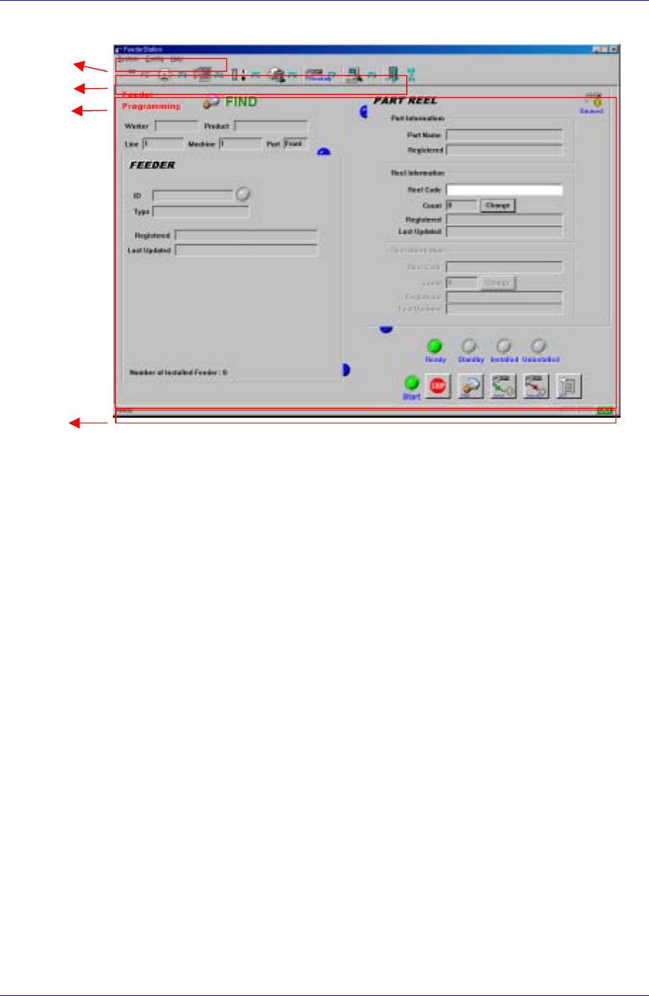
3.1.1. Structure of system screen
The structure of system screen is as follows.
Main menu
Consists of System, Database, Config, and Help. Detailed information on each menu
will be provided later
Toolbar
Located under the Main menu. It consists of 7 icons. Each icon has the respective
keyboard shortcut. When a menu is executed, the respective icon turns gray and it is
disabled. When another menu is executed, it is enabled again. When the mouse
pointer is located on a menu, the respective tool tip appears, giving a brief description
of the menu.
Execution window
This is where the task is actually carried out. The results of commands such as
various queries and registration are displayed here.
Status Bar
3-1
Samsung Intelligent Feeder System
Displays messages.
Main menu
Toolbar
Execution window
Status Bar
Figure 3-1. Main screen structure
Effects of using Feeder Station
For PCB assembly operations, Component Placer needs to register the components to
be mounted on the PCB, decide placement points, and install the respective
components on the feeder base. After the positions of each placement point and
component have been decided and the PCB has been supplied, the data on the
component to mount is obtained from the mounting program. Then the respective
component is picked up from the feeder base and it is placed on the placement point
on the PCB. At this time, the component is inspected by the attached camera while it
is on the move. When the operation is finished, the PCB is transferred to the next
process. As a series of operations requiring substantial amount of time are carried out
by the equipment, the equipment operation rate is lowered.
This program provides various programs that minimize equipment preparation time to
improve equipment operation rate. OLP( Off-Line program) and IT Feeder Station are
examples of this.
Equipment preparation time is minimized by using a device called Docking Cart. It
allows preparation of component placement operation in advance Off-Line.
Feeder Station is a program to mount the PartReel registered in the Part Station in the
Feeder. It creates Feeder data so that it is possible to find out which components are
registered in the feeder mounted on the equipment by synchronizing the Feeder and
Reel.
Each Feeder should contain a unique RF-ID inside and the Reel should be registered
in the Part Station first.
3-2
Feeder Station
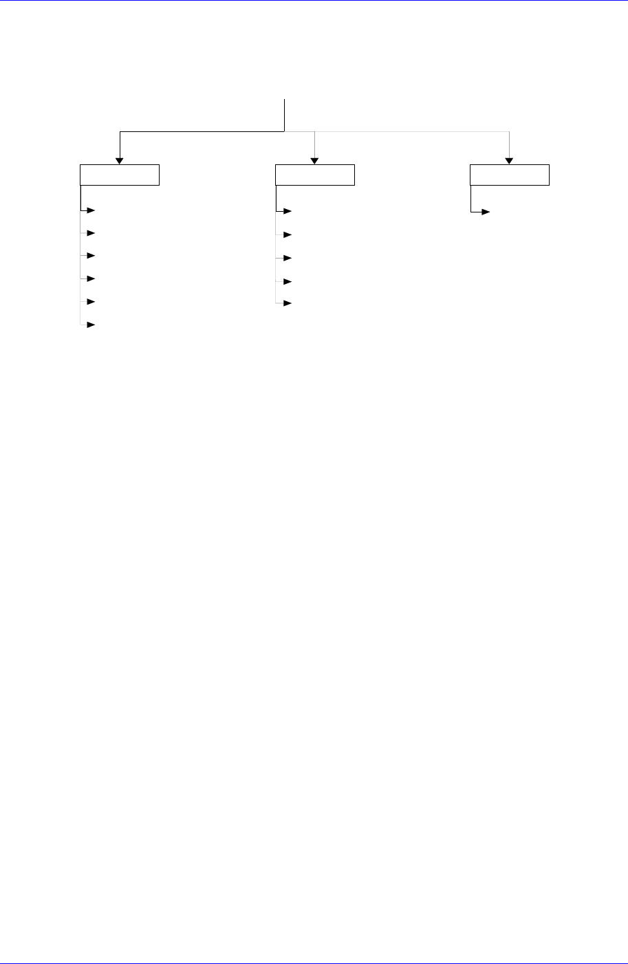
3.2. Structure of the Main menu
The structure of the Main Menu of Feeder Station is as follows.
System Config Help
Feeder Info. (F2)
PartReel List (F3)
Feeder List (F4)
Part List (F5)
W aste Reel (F6)
Exit (Alt+F4)
Tool Bar
Status Bar
Modify Feeder (Ctrl+M)
System Config (F9)
About Feeder Station
Feeder Station
Ver 2.0
Database Connect (Ctrl+F5)
Figure 3-2. IT Feeder Feeder Station Main Menu Tree
3.2.1. System
Feeder Info.
Searches, installs or uninstalls the reels registered in the Part Station in the Feeder.
Part Reel List
Searches the Part Reels registered in the Part Station.
Feeder List
Searches the registered Feeders with various conditions and searches whether Reels
are installed in the Feeder or not.
Part List
Searches the Parts registered in the Part Station.
Waste Reel
Deletes used up PartReels.
Exit
Ends Feeder Station.
3.2.2. Config
Tool Bar
Removes or restores the tool bar at the top of the screen.
Status Bar
Removes or restores the status bar at the bottom of the screen.
Modify Feeder
Modifies the registered Feeder data.
System Config
Specifies the Local DB, Master DB, barcode scanner type, and RF-ID Reader
3-3