Betriebsanleitung_HF3_14_de.pdf - 第597页
10 2KE0041502 - englisch_BA 04.1 1.2010 ENGLISH 2 . DESCRIPTION OF THE PROCESS COOLER The process cooler is a unit ready for plug-in and is equipped with refrigeration and water circuits including all fittings and regula…

9
2KE0041502 - englisch_BA
04.11.2010
ENGLISH
1.5.2 Operation
The owner or the operator of the process cooler is obligated to establish emergency
practices (in the case of accidents and malfunctions). A short version of the operating
instructions must be drawn up by the operator – based on this present Operating Manual – and
made known to the employees.
The quick reference guide must be clearly legible and affixed in the immediate
vicinity of the process cooler.
See Sample Quick Reference Guide.
The owner or operator of a system is obligated to keep a logbook for the process
cooler.
The system logbook must either be available on site near the process cooler, or in the event
that the data are stored in a computer of the owner or operator, a printout of the log must be
kept in the vicinity of the process cooler. It must be ensured that these data are accessible to
qualified persons for the performance of repairs and requalification/repeat tests.
See Sample System Log
1.5.3 Repeat/Requalification Testing
To ensure compliance with minimum safety and health requirements as set forth in standard
EN 378, regular testing (requalification testing) of the process coolers is to be carried out by
competent persons.
The operator is responsible for the performance of the retests.
(See Chapter Repeat Testing).
1.6 Purpose of the Process Cooler
The process cooler described in this manual is designed exclusively for the cooling of water
within the specified operating temperature limits.
1. For Your Safety
10
2KE0041502 - englisch_BA
04.11.2010
ENGLISH
2. DESCRIPTION OF THE PROCESS COOLER
The process cooler is a unit ready for plug-in and is equipped with refrigeration and water
circuits including all fittings and regulating/control devices required for automatic operation.
The heat extracted from the water is given off to the ambient air via the refrigeration circuit – by
means of the fans.
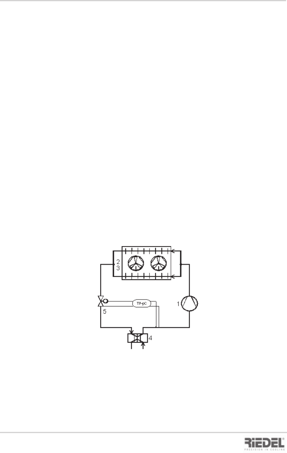
2.1 Refrigeration Circuit
The refrigeration circuit is a closed-loop system in which the refrigerant circulates as the
working medium.
The water heated by the equipment to be cooled is re-cooled in the evaporator (3). The liquid
refrigerant is thereby passed through the piping in a counter-flow arrangement with respect to
the water. The refrigerant evaporates as it takes up the waste heat from the cooling water of the
equipment to be cooled.
The vaporised refrigerant is drawn in by the compressor (1) and is then compressed (rise in
pressure and temperature). The refrigerant also absorbs the heat of the compressor motor; this
heat is given off to the surrounding air by the condensers (2) - in the form of waste heat –by
means of the fan.
The refrigerant is thus liquefied and is passed to the inlet of the expansion valve (4) via the
liquid receiver, the shut-off valve, the filter drier and the sight glass. The expansion valve permits
liquid refrigerant to enter the evaporator as a function of the temperature.
The circuit is now complete.
Block flow diagram, refrigerant circuit
2. Description of the Process Cooler

11
2KE0041502 - englisch_BA
04.11.2010
ENGLISH
2.2 Water Circuit
(See also flow diagram of pipes and instruments)
2.2.1 Single Circuit System with Tank
The water circuit with its integrated tank is designed as a system open to the atmosphere. The
constancy of the water outlet temperature is governed by the water volume inside the tank. The
pump conveys the water out of the tank to the equipment to be cooled and back to the tank via
the evaporator.
2.3 Cooling Air Supply
The heat transferred to the evaporator upon cooling the water as well as the heat of the
compressor motors are absorbed by the refrigerant and given off to the cooling air in the
condenser.
As cooling air the ambient air is used which is drawn through the condenser by the fan(s),
warmed and then discharged in upward direction
It must be ensured that the cooling air can be drawn in and discharged without any
obstructions and adequate air changes for heat dissipation away from the installation
site of the process cooler take place.
(see also Section Installation)
2. Description of the Process Cooler