YS100_Ope_E.pdf - 第155页
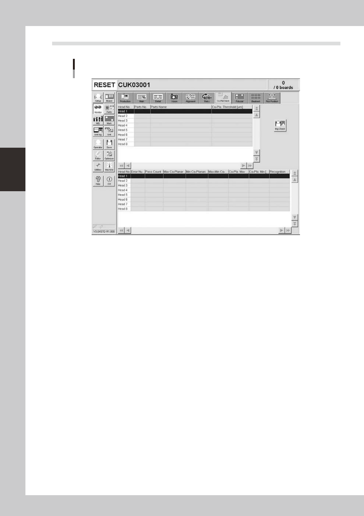
3-30 3 Starting and ending pr oduction 3.11 Coplanarity checker Monitor: Co-PlaCheck (Coplanarity Check) 24319-L1-00 • Head No. Displays the head number currently being used. • Par ts No. Displays the part number current…
3-29
3
Starting and ending production
n
What is "watch-and-wait" mode?
When "watch-and-wait" mode is entered by pressing the [Current Check] or [All Check] button, the abnormal pickup rate
at that point is stored and the color of "red" row(s) changes to "pink" temporarily. If the pickup rate then improves or
deteriorates from that point onward, the color of the row(s) changes to report the new state to the operator.
For example, after an abnormal pickup rate is stored in "watch-and-wait" mode, if the problem is eliminated and
operation resumed, and the pickup rate improves, then the color of the row(s) changes from "pink" to "yellow" to show
an improvement has been made. Conversely, if the pickup rate becomes even worse, then the color changes from "pink"
back to "red" to show the troubleshooting was ineffective.
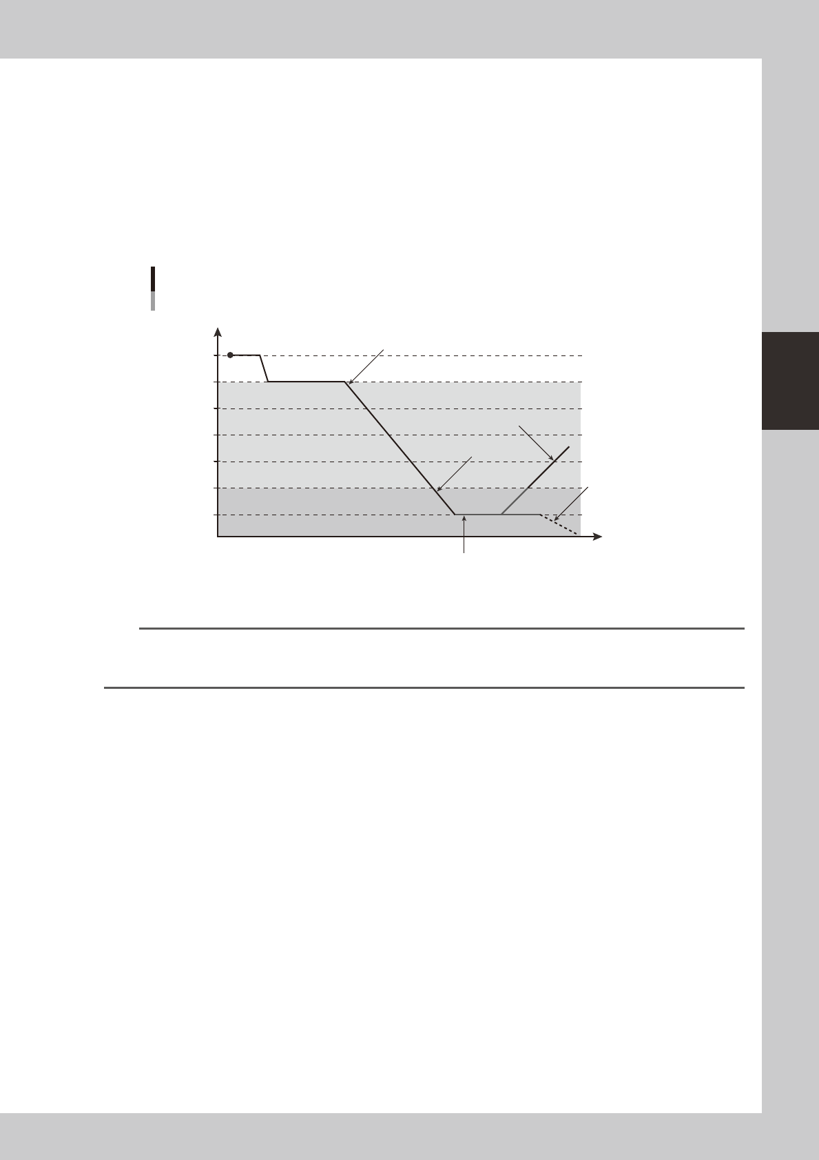
The colors in the following graph show changes in the pickup rate, using an example when "caution (yellow)" is set to
99.00% and "warning (red)" to 95.00%.
Color transitions per changes in pickup rates
100
99
98
97
96
95
94
Pickup rate %
Time
Changes to yellowStart (white)
Changes to yellow (better pickup rate)
Changes to red
Changes to red
(worse pickup rate)
Pressing the [Current Check] or [All Check] button enables
"watch-and-wait" mode and changes the color of "red" row(s) to
"pink".
23301-L1-00
TIP
When "watch-and-wait" mode is enabled, the color of the "red" row(s) showing an abnormal pickup rate changes to
"pink" and the pickup rate at that point is stored. The "pink" color then changes according to changes in the pickup
rate from that point onward.
3-30
3
Starting and ending production
3.11 Coplanarity checker
Monitor: Co-PlaCheck (Coplanarity Check)
24319-L1-00
• Head No.
Displays the head number currently being used.
• Parts No.
Displays the part number currently being used.
• Parts Name
Displays the part name currently being used.
• Co-pla. Threshold [μm]
Displays the coplanarity tolerance that was set in parts information.
• Error Number
Displays coplanarity error numbers.
• Pass Count
Displays the number of images that were captured during coplanarity check.
• Max. Co-planarity Pos.
Displays the lead number that was measured as the maximum coplanarity value.
• Min. Co-planarity Pos.
Displays the lead number that was measured as the minimum coplanarity value.
• Max-Min Co-planarity [μm]
Displays the coplanarity measurement result.
• Co-planarity Max. [μm]
Displays the maximum coplanarity value.
• Co-planarity Min. [μm]
Displays the minimum coplanarity value.
• Recognition Height
Displays the recognition height (height to underside of components).