YS100_Ope_E.pdf - 第63页
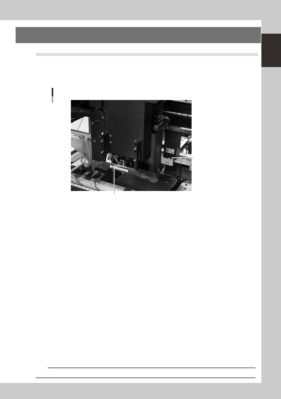
1-28 1 Part names and functions 8.2 T ape cutting during board conveying All tape cutters can operate with no special restrictions w hile a board is being convey ed to the exit after component mounting is completed. Howe…

1-27
1
Part names and functions
8. Tape cutter (option)
Tape cutters are internally installed as options for the YS series. There are two types of tape cutting during
automatic operation. Both types can be jointly used.
Tape cutting is available in the following two types:
• During component mounting : Tape is cut during component mounting after completion of pickup.
• During board conveying : Tape is cut while each board is conveyed to exit after component mounting.
n
Tape cutter open/close timing
• Return to origin (close
→
open)
Opens all tape cutters immediately after return-to-origin operation.
• During start and reset of automatic operation (close
→
open)
Closes all tape cutters and then opens them.
• During machine power-off (open
→
close)
When turning off the machine power, a confirmation dialog box appears to help navigate the processing method. Pressing
the OK button closes all tape cutters.
8.1 Tape cutting during component mounting
Tape is cut during component mounting based on the actual feed length (tape feed length) that the tape is fed
from the feeder.
• Tape feed length
This is the length calculated for each feeder from the feed pitch and the tape feed count of the components during
component pickup. Tape cut length is decided during component mounting based on the longest tape length fed into one
cutter.
• Feed pitch
Feed pitch is calculated using the feed pitch set (in memory) for the SS feeder at each station, or the feed pitch set in the
board data.
• Tape cut timing
Tape is cut after component recognition during the mounting operation.
However, no component is mounted if the tape cutting has not finished before feeding of the next component group for
pickup starts.
• Tape cutting conditions
Tape must be cut during component mounting, in the period from "Standard cut length" to "Maximum cut length" that
were preset in the machine settings.
1. Tape is always cut when tape feed length exceeds maximum cut length.
2. Tape is usually cut when tape feed length exceeds the standard cut length.
n
NOTE
Tape feed length being counted when tape cutting ends normally is reset.
n
Delaying the tape cutting
• If feeders on multiple tape cutters are simultaneously longer than the standard cut length and shorter than the
maximum cut length, then the tape with longer feed lengths are cut, and cutting of tape with shorter feed lengths is
delayed.
• Even if longer than the standard cut length, the tape cutting is delayed to allow component mounting to proceed in
cases where the number of heads used in this pickup group is fewer than the specified number of heads.

1-28
1
Part names and functions
8.2 Tape cutting during board conveying
All tape cutters can operate with no special restrictions while a board is being conveyed to the exit after
component mounting is completed.
However, if there has been no tape feed whatsoever in tape feeders installed on the rear feeder plate since the
last tape cutting, then the rear tape cutters will not operate.
• Tape cut timing
Tape cutting operates at the timing that the boards are unclamped and conveyed to the exit after component mounting is
completed.
• Tape cutting conditions
Tape cutting is performed each time a board is conveyed to the exit after completing component mounting, and tape
cutting starts on all tape cutters that are set enabled.
8.3 Restrictions (caution)
Conditions affecting component mounting time
• If the tape feed lengths on the front and rear tape cutters simultaneously exceed the maximum cut length, then the
machine might delay component mounting to allow each tape cutter to cut the tape alternately.
• If the tape cutting speed drops due to a breakdown such as in the tape cutter valves or cylinder, then the machine
might delay component mounting.
Cautions for tape cutting during board conveying
Use caution when using board data where there is a large component feed length per feeder for each board, since the
tape that was cut off might hang up on the tape eject slot and does not reach the trash box.
Setting the standard cut length and maximum cut length
Hangs ups tend to occur during tape cutting performed during component mounting if the standard cut length and
maximum cut length were set to a large figure. Set these to a shorter figure if the tape does not easily eject after tape
cutting.
As a general guide, set the the standard cut length to 80mm, and the maximum cut length to 120mm.
n
NOTE
Operation buttons will be disabled during emergency stop or if an interlock is triggered.
1-29
1
Part names and functions
9. Other options
9.1 Side-view camera
The side-view camera is installed on the X-axis at the front of the multi-view camera. The side-view camera
recognizes horizontal images such as for the component pickup status, by using lighting installed for the
side-view camera. This allows the machine to detect component pickup errors and abnormal pickup, or find
dirt or debris adhering to the nozzle.
Side-view camera
Side-view camera
Lighting unit (with cover removed)
23114-L1-00
The side-view camera has the following functions:
n
Pickup error detection function
Normal mode
Detects component pickup errors to prevent "no placement errors".
Normal mode operates even when nozzles are changed after nozzle cleaning, etc.
Detail mode
Detects component pickup errors to prevent "no placement errors".
Checks for abnormal component pickups such as tilted, vertical or horizontal pickups based on the component thickness
tolerance set by the users.
n
Dirty nozzle sensing function
If the side-view camera shows "no component" even when the multi-view camera shows "component present", the
machine determines that the nozzle tip is "dirty" and a warning message appears. This serves as an accurate guide for
nozzle cleaning periods.
n
Component discard skip
This function skips the discard operation when the side-view camera shows "no component".
This eliminates unneeded operation when no component was picked up and prevents a loss of cycle time during
production.
n
Remaining component check function
This detects whether a component still remains at a nozzle tip after components were mounted or discarded.
n
Inverted component check function
In the recognition process after a component is picked up by a nozzle, this function checks if the front and back sides of
the component are inverted. It also simultaneously checks if that component size fits within the angle-of-view of the
side-view camera.
An error message appears if recognition shows the component front and back sides are inverted or that component will
not fit within the angle-of-view.
n
NOTE
Refer to "Programming Manual" for side-view camera parameter settings.