00191021-02.pdf - 第80页
2 Functions for the Adj ustment of the Machine User’s Manual Test Program S ITEST 2.1 Axis Functions Softw are Version 403.xx Edition 12/97 2 - 16

User’s Manual Test Program SITEST 2 Functions for the Adjustment of the Machine
Software Version 403.xx Edition 12/97 2.1 Axis Functions
2 - 15
●
If the selected axis is to be positioned in the continuous run mode, click on the
Continuous run
button. The setting box for the positioning data opens. All further steps are the same as described in
section 2.1.1.
●
If the tacho is to be adjusted to the final speed, click on the
Tacho adjustment...
button. The continu-
ous run for the adjustment of the tacho is started.
All further steps are the same as described in section 2.1.1.
●
Click on the
Counting error
button if you wish to start a check of the counting errors for the currently
active axis. On starting the check, a dialog box opens in which a value is displayed after the check
representing the counting error of the axis (in digits or "counts").
●
To acknowledge this display, click on the
OK
button in the dialog box.
●
If you wish to change the values for the machine parameters "Zero point cor.value", "Maximum posi-
tion" and "Minimum position", click on the
Positions...
button.
A setting box opens. All further steps are the same as described in section 2.1.1.
●
If you wish to view the machine parameter values, click on the
Positioning data...
button.

2 Functions for the Adjustment of the Machine User’s Manual Test Program SITEST
2.1 Axis Functions Software Version 403.xx Edition 12/97
2 - 16
User’s Manual Test Program SITEST 2 Functions for the Adjustment of the Machine
Software Version 403.xx Edition 12/97 2.2 Head Board
2 - 17
2.2 Head Board
The functions of the head board are used to test the respective placement head. Normally, the test is per-
formed with the aid of the "Head continuous run" function (see display "RV head functions", Fig. 0.3.5).
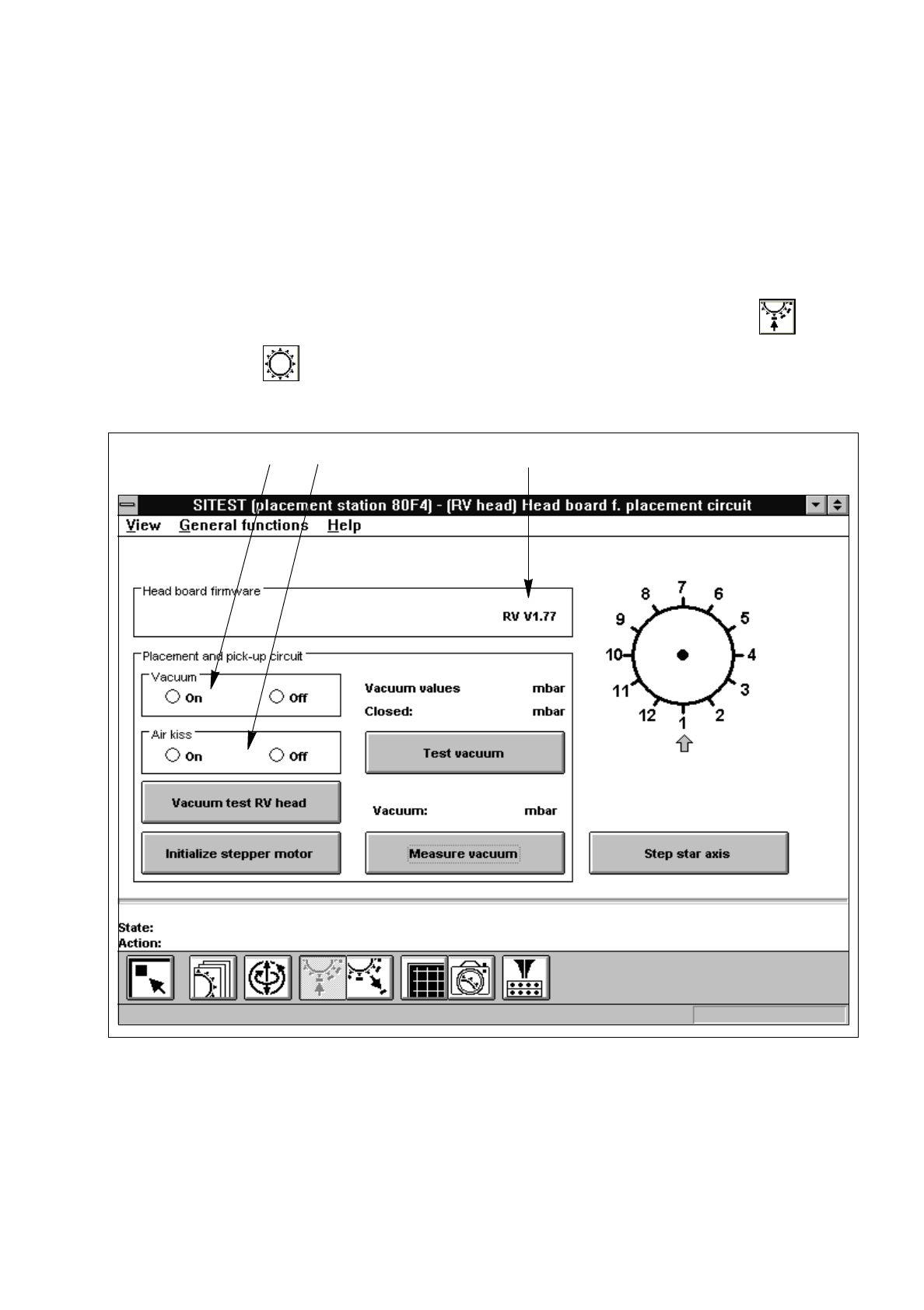
2.2.1 Functions of the RV Head in the Placement and Pick-Up Circuits
●
If you wish to test the head functions in the placement and pick-up circuits, click on the icon in
the "RV head" display (see Fig. 0.3.5) to switch to the "Head board RV head, placement and
pick-up circuit".
Fig. 2.2.1 "Head board RV head, placement and pick-up circuit" Display
Legend pertaining to
Fig. 2.2.1
➀
to switch the vacuum on/off
➁
to switch the air-kiss function at the placement station on/off
➂
version number of the firmware
➀
➁
➂