Anritsu_MG3692C.PDF - 第10页
10 Internal LF and Pulse Generators (Option 27) An internal pulse generator and two internal waveform generators are added, one provid- ing a frequency or phase modulating signal and the other an amplitude modulating sig…
9
Frequency Generator Multiplication/Division Ratios:
Phase Modulation:
Frequency Modulation:
Modulation
Frequency/Phase Modulation (Option 12)
Option 12 adds frequency and phase modulation, driven externally via a rear panel BNC
connector, 50 Ω. For internal modulation, add Internal LF Generator and Pulse Generator
Option 27. Frequency/Phase Modulation is not available <10 MHz with Option 22.
For the most accurate FM and ΦM measurements, Bessel Null methods are used.
When verifying FM and ΦM, the use of the “carrier null” technique is recommended.
Measured residual FM effects must be subtracted from modulation meter measurements.
Frequency Range Divide Ratio, n
< 10 MHz (Option 22) modulation not available
≥ 10 MHz to ≤ 15.625 MHz (Option 4) 256
> 15.625 MHz to ≤ 31.25 MHz (Option 4) 128
> 31.25 MHz to ≤ 62.5 MHz (Option 4) 64
> 62.5 MHz to ≤ 125 MHz (Option 4) 32
> 125 MHz to ≤ 250 MHz (Option 4) 16
> 250 MHz to ≤ 500 MHz (Option 4) 8
> 500 MHz to ≤ 1050 MHz (Option 4) 4
> 1050 MHz to ≤ 2200 MHz (Option 4) 2
> 10 MHz to ≤ 2000 MHz (Option 5) 1
> 2 GHz to ≤ 20 GHz 1
> 20 GHz to ≤ 40 GHz 1/2
> 40 GHz to ≤ 67 GHz 1/4
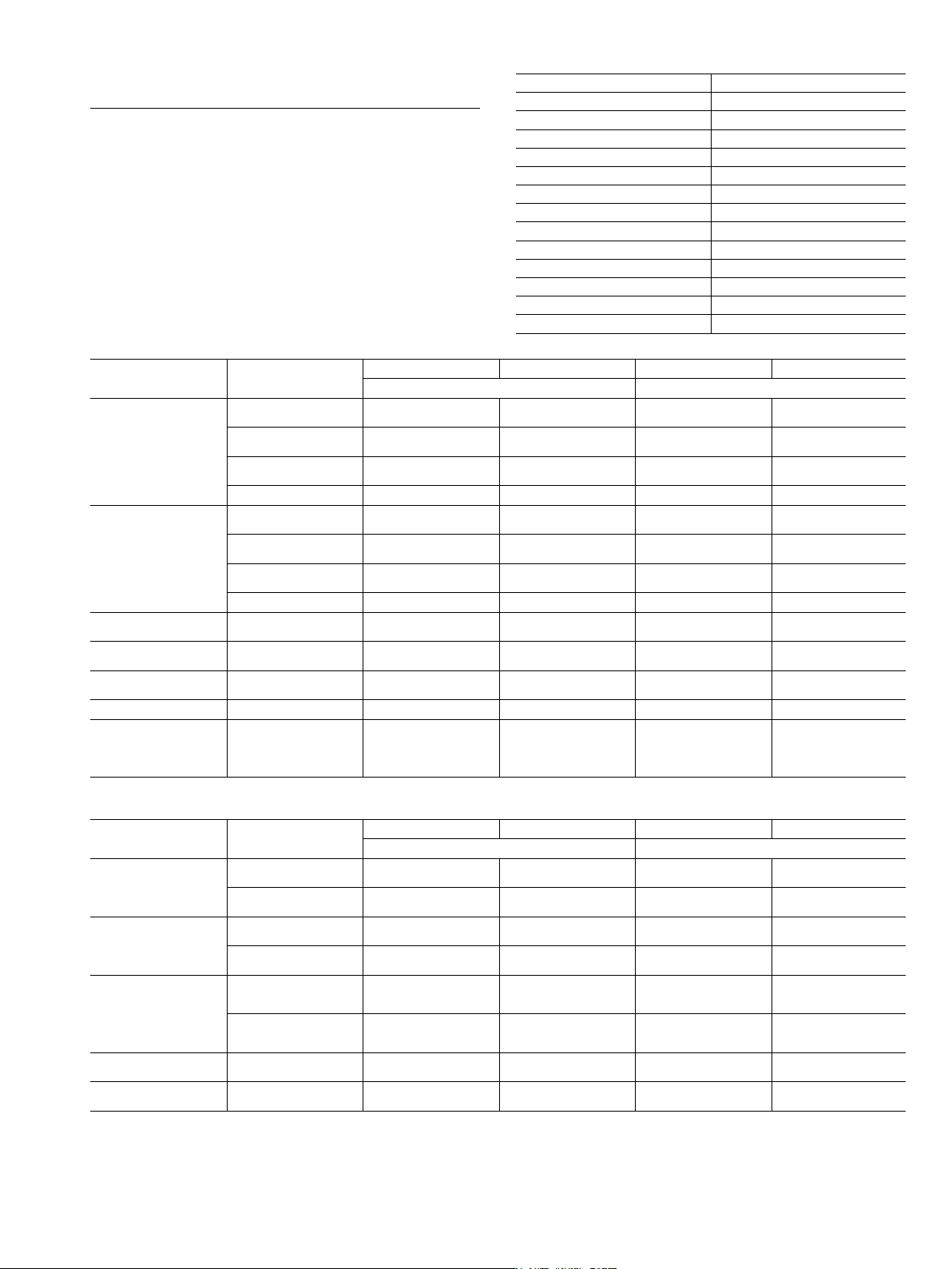
Parameter Modes
Conditions Specifications Conditions Specifications
for all Frequencies other than < 2.2 GHz with Option 4 for Frequencies < 2.2 GHz with Option 4
Deviation
Locked Rate= 1 kHz to 8 MHz
± [Lesser of 10 MHz or 300 *
(mod rate)]/n
Rate = 1 kHz to (Lesser of
8 MHz or 0.03 * Fcarrier)
± [Lesser of 10 MHz or
300 * (mod rate)]/n
Locked Low-noise Rate= 50 kHz to 8 MHz
± [Lesser of 10 MHz or
3 * (mod rate)]/n
Rate = 50 kHz to (Lesser of
8 MHz or 0.03 * Fcarrier)
± [Lesser of 10 MHz or
3 * (mod rate)]/n
Unlocked Narrow Rate= DC to 8 MHz ± 10 MHz/n
Rate = DC to (Lesser of
8 MHz or 0.03 * Fcarrier)
± (10 MHz)/n
Unlocked Wide Rate= DC to 100 Hz ± 100 MHz/n Rate = DC to 100 Hz ± (100 MHz)/n
Bandwidth (3 dB)
Locked 1 kHz to 10 MHz
1 kHz to (Lesser of 10 MHz or
0.03 * Fcarrier)
Locked Low-noise 30 kHz to 10 MHz
30 kHz to (Lesser of 8 MHz or
0.03 * Fcarrier)
Unlocked Narrow DC to 10 MHz
DC to (Lesser of 10 MHz or
0.03 * Fcarrier)
Unlocked Wide DC to 100 Hz DC to 100 Hz
Flatness Locked Rate= 10 kHz to 1 MHz ± 1 dB relative to 100 kHz
Rate = 10 kHz to (Lesser of
1 MHz or 0.01 * Fcarrier)
± 1 dB relative to 100 kHz
Accuracy
Locked and Low-noise
Unlocked Narrow
Rate= 100 kHz sinewave
Int. or 1 Vpk Ext.
10% (5% typical)
Rate= 100 kHz sinewave
Int. or 1 Vpk Ext.
10% (5% typical)
Incidental AM
Locked and Low-noise
Unlocked Narrow
1 MHz Rate, ± 1 MHz Dev. < 2% typical
Rate and Dev.= Lesser of 1 MHz
or 0.01 * Fcarrier
< 2% typical
Harmonic Distortion Locked 10 kHz Rate, ± 1 MHz Dev. < 1% Rate = 10 kHz, Dev.= ± (1 MHz)/n < 1%
External Sensitivity
Locked
Locked Low-noise
Unlocked Narrow
Unlocked Wide
(± 1V maximum input)
± (10 kHz/V to 20 MHz/V)/n
″
″
± (100 kHz/V to 100 MHz/V)/n
(± 1 Vpk maximum input)
± (10 kHz/V to 20 MHz/V)/n
″
″
± (100 kHz/V to 100 MHz/V)/n
Parameter Modes
Conditions Specifications Conditions Specifications
for all Frequencies other than < 2.2 GHz with Option 4 for Frequencies < 2.2 GHz with Option 4
Deviation
Narrow Rate= DC to 8 MHz
± [Lesser of 3 rad or
(5 MHz/mod rate)]/n
Rate = DC to (Lesser of
8 MHz or 0.03 * Fcarrier)
± [Lesser of 3 rad or
(5 MHz/mod rate)]/n
Wide Rate= DC to 1 MHz
± [Lesser of 400 rad or
(10 MHz/mod rate)]/n
Rate = DC to (Lesser of
1 MHz or 0.03 * Fcarrier)
± [Lesser of 400 rad or
(10 MHz/mod rate)]/n
Bandwidth (3 dB)
Narrow DC to 10 MHz
DC to (Lesser of 10 MHz or
0.03 * Fcarrier)
Wide DC to 1 MHz
DC to (Lesser of 1 MHz or
0.03 * Fcarrier)
Flatness
Narrow Rate= DC to 1 MHz ± 1 dB relative to 100 kHz
Rate = DC to (Lesser of 1 MHz
or 0.01 * Fcarrier)
± 1 dB relative to 100 kHz rate
Wide Rate= DC to 500 kHz ± 1 dB relative to 100 kHz
Rate = DC to (Lesser of 500 kHz
or 0.01 * Fcarrier)
± 1 dB relative to 100 kHz rate
Accuracy Narrow and Wide
100 kHz Internal or
1Vpk External, sine
10%
100 kHz Internal or
1 Vpk External, sine
10%
External Sensitivity
Narrow
Wide
(± 1 V maximum input)
± (0.0025 rad/V to 5 rad/V)/n
± (0.25 rad/V to 500 rad/V)/n
(± 1 Vpk maximum input)
± (0.0025 rad/V to 5 rad/V)/n
± (0.25 rad/V to 500 rad/V)/n
10
Internal LF and Pulse Generators (Option 27)
An internal pulse generator and two internal waveform generators are added, one provid-
ing a frequency or phase modulating signal and the other an amplitude modulating signal.
This Internal LF and Pulse Generators option can only be ordered in combination with
either FM/ΦM, AM, or Pulse options, 12, 14, and 26 respectively.
Waveforms: Sinusoid, square-wave, triangle, positive ramp, negative ramp, Gaussian
noise, uniform noise. (Check Option 10 for User-Defined)
Rate:
0.1 Hz to 10 MHz sinusoidal
0.1 Hz to 1 MHz square-wave, triangle, ramps
Resolution: 0.1 Hz
Accuracy: Same as instrument timebase ± 0.014 Hz
Waveform Outputs: Two BNC connectors on the rear panel, FM/ΦM OUT and AM OUT
Pulse Modes: Singlet, doublet, triplet, quadruplet
Pulse Triggers: Free-run, triggered, gated, delayed, triggered with delay, swept-delay
Pulse Inputs/Outputs: Video pulse and sync out, rear-panel BNC connectors
① For 50 GHz and 67 GHz units, overshoot > 40 GHz is 20% typical at rated power.
② Period must be longer than the sum of delay and width by 5 clock cycles minimum.
③ Rise time and Pulse Width Compression, > 20 GHz, degrades by 2 ns,
with High Power Option 15.
* Typical
Amplitude Modulation (Option 14)
Option 14 adds amplitude modulation, driven externally via a rear panel BNC connector 50 Ω.
For internal modulation, add Internal LF and Pulse Generators Option 27.
All amplitude modulation specifications apply at 50% depth, 1 kHz rate, with RF level set
6 dB below maximum specified leveled output power, unless otherwise noted. Amplitude
Modulation is not available < 10 MHz with Option 22.
AM Depth (typical): 0-90% linear; 20 dB log
AM Bandwidth* (3 dB):
DC to 50 kHz minimum
DC to 100 kHz typical
Flatness (DC to 10 kHz rates): ± 0.3 dB
Accuracy:
Reading ± 5%
Distortion: < 5% typical
Incidental Phase Modulation (30% depth, 10 kHz rate):
<0.2 radians typical
External AM Input: Log AM or Linear AM input, rear-panel BNC, 50 Ω input impedance.
For internal modulation, add LF Generator Option 27.
Sensitivity:
Log AM: Continuously variable from 0 dB per volt to 25 dB per volt.
Linear AM: Continuously variable from 0% per volt to 100% per volt.
Maximum Input: ± 1 Vpk
*Typical below 2.2 GHz, when ordered with Options 4 and 15.
Pulse Modulation (Option 26)
Option 26 adds pulse modulation, driven externally via a rear panel BNC connector, TTL.
For internal modulation, add Internal LF and Pulse Generators Option 27.
Pulse modulation specifications apply at maximum rated power, unless otherwise noted.
Pulse modulation is not available < 10 MHz with Option 22.
On/Off Ratio: > 80 dB (> 70 dB with high power Option 15)
Minimum Leveled Pulse Width:
100 ns, ≥1 GHz
1 µs, <1 GHz
Minimum Unleveled Pulse Width: < 10 ns
Level Accuracy Relative to CW (100 Hz to 1 MHz PRF):
± 0.5 dB, ≥ 1 µs pulse width
± 1.0 dB, < 1 µs pulse width
Pulse Delay (typical): 50 ns in External Mode
PRF Range:
DC to 10 MHz, unleveled
100 Hz to 5 MHz, leveled
External Input: Rear-panel BNC. For internal modulation, add Pulse Generator Option 27
Drive Level: TTL compatible input
Input Logic: Positive-true or negative-true, selectable from modulation menu.
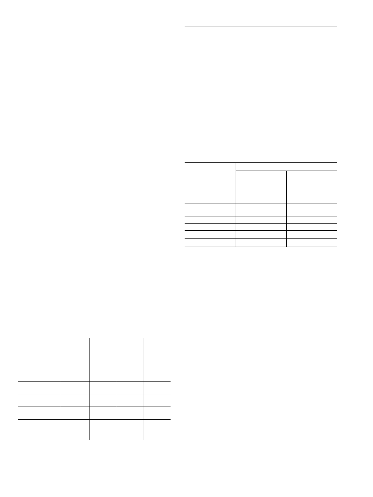
Pulse
Parameter
Selectable Clock Rate
Narrow (100 MHz) Wide (10 MHz)
Pulse Width 10 ns to 160 ms 100 ns to 1.6 s
Pulse Period
②
100 ns to 160 ms 600 ns to 1.6 s
Variable Delay
Singlet 0 ms to 160 ms 0 s to 1.6 s
Doublet 100 ns to 160 ms 300 ns to 1.6 s
Triplet 100 ns to 160 ms 300 ns to 1.6 s
Quadruplet 100 ns to 160 ms 300 ns to 1.6 s
Resolution 10 ns 100 ns
Accuracy 10 ns (5 ns typical) 10 ns (5 ns typical)
Frequency
Range
Rise and Fall
Time
(10% to 90%)
Overshoot
Pulse Width
Compression
Video
Feedthrough
≥ 10 MHz to < 31.25 MHz
(Opt. 4)
400 ns* 33%* 40 ns* ± 70 mV*
≥ 31.25 MHz to < 125 MHz
(Opt. 4)
90 ns* 22%* 12 ns* ± 130 mV*
≥ 125 MHz to < 500 MHz
(Opt. 4)
33 ns* 11%* 12 ns* ± 70 mV*
≥ 500 MHz to < 2200 MHz
(Opt. 4)
15 ns* 10% 12 ns* ± 50 mV*
≥ 10 MHz to < 1000 MHz
(Opt. 5)
15 ns, 10 ns* 10% 8 ns* ± 30 mV*
≥ 1 GHz to < 2 GHz
(Opt. 5)
10 ns, 5 ns* 10% 8 ns* ± 30 mV*
≥ 2 GHz to 67 GHz
③
10 ns, 5 ns* 10%
①
8 ns* ± 30 mV*
11
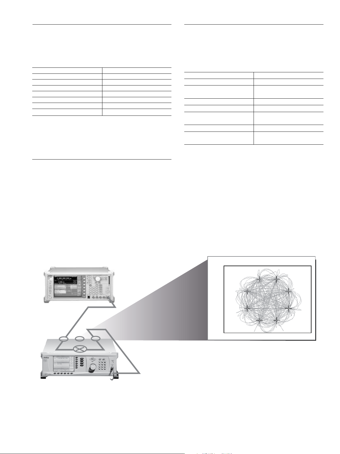
TRACE A: Ch1 8PSK Meas Time
1.5
-1.5
-1.9607643757 1.96078437567
I - Q
300
M
/div
MG3700A
MG3690C
Carrier Frequency = 38.000 GHz
RF
IF
LO
IF Up-Conversion (Option 7) Application and Setup
IF Up-Conversion (Option 7)
Option 7 adds an internal mixer that can be used for the generic up-conversion of
an IF signal. The mixer’s RF, LO, and IF ports are made available at the rear panel
of the MG3690C, via three female K-Connectors. The typical application will feed the
MG3690C microwave output, which can be moved to the rear panel via option 9K,
to the mixer’s LO port. An external IF signal will be fed to the mixer’s IF port. The
new up-converted signal will be available at the mixer’s RF port.
The IF Up-Conversion option is particularly useful to create a microwave frequency
IQ-modulated signal. Lower frequency IQ-modulated RF sources are readily
available, such as the Anritsu MG3700A. Option 7’s IF input can be used to feed in
an IQ-modulated signal from an MG3700A, up-converting it to as high as 40 GHz
with an MG3694C. A typical setup is shown below.
User-Defined Modulation Waveform Software (Option 10)
An external software package provides the ability to download user-defined
waveforms into the internal LF Generator’s (Option 27) memory. The MG3690C
provides as standard with the LF Generator sinusoidal, square-wave, triangle,
positive ramp, Gaussian noise, and uniform noise waveforms.
Two look-up tables of 65,536 points can be used to generate two pseudo-random
waveforms, one for amplitude modulation and the other for frequency or phase
modulation. The download files are simple space-delimited text files containing
integer numbers between 0 and 4095, where 0 corresponds to the minimum
modulation level and 4095 the maximum.
In addition to the capability of downloading custom waveforms, the software
offers a virtual instrument modulation panel. Custom modulation setups with user
waveforms can be stored for future use. For IFF signal simulation, the internal
generators can be synchronized. They can also be disconnected from the internal
modulators, making the low frequency waveforms available at the rear panel for
external purposes.
Scan Modulation (Option 20)
Option 20 adds a microwave linearly controlled attenuator to provide deep AM ca-
pability. This modulator is inserted outside the leveling loop but before the optional
step attenuator. It is switched in and out of the RF path. Scan modulation is driven
externally only.
One application of this feature is storing an antenna pattern wave form in memory
and using it to feed the external input to the scan modulator, Option 20.
Mixer Type Double Balanced
RF, LO Range 1 GHz to 40 GHz
IF Range DC to 700 MHz
Conversion Loss 10 dB Typical
Max Power into any Port 30 dBm
Isolation, RF to LO 23 dB
LO Drive Level (recommended) +10 dBm to +13 dBm
Input P
1 dB
+3 dBm Typical
Frequency Range 2 GHz to 18 GHz
Attenuation Range 0 dB to 60 dB
Flatness/Accuracy
± 1.5 dB/± 1.5 dB, 0 to 40 dB
± 3 dB/± 2 dB, 40 to 60 dB
Step Response < 1 µs
Sensitivity –10 dB/V
Modulation Bandwidth
20 kHz (small signal)
5 kHz (large signal)
Insertion Loss < 6 dB (when engaged)
Input
Rear Panel BNC connector
High Impedance