Anritsu_MG3692C.PDF - 第12页
12 Millimeter W ave Multipliers 1 - 63850 series (Option 18 recommended for DC bias.) 63850 series external, waveguide output, multipliers are available for banded frequency coverage up to 325 GHz. These external multipl…
11
TRACE A: Ch1 8PSK Meas Time
1.5
-1.5
-1.9607643757 1.96078437567
I - Q
300
M
/div
MG3700A
MG3690C
Carrier Frequency = 38.000 GHz
RF
IF
LO
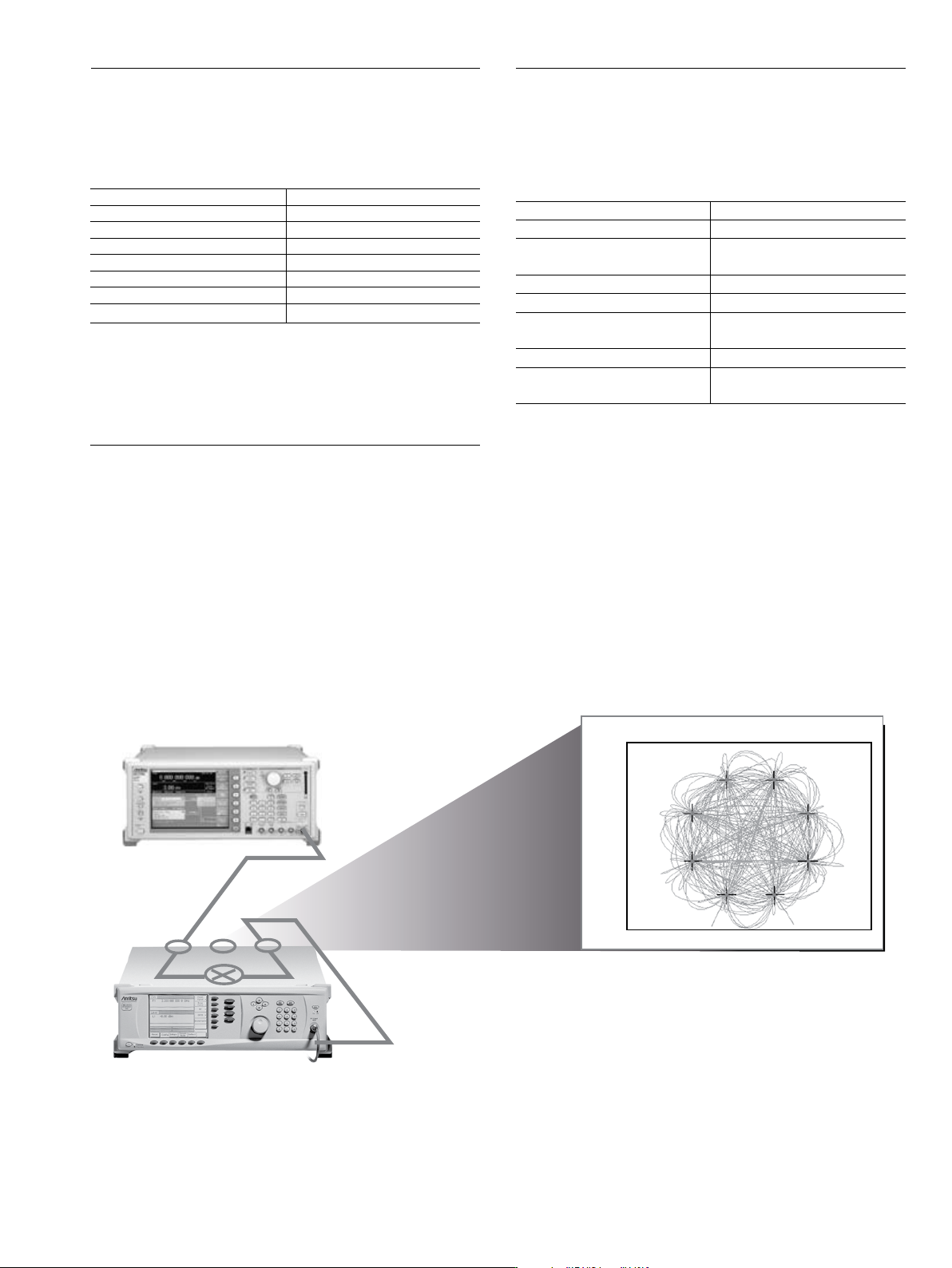
IF Up-Conversion (Option 7) Application and Setup
IF Up-Conversion (Option 7)
Option 7 adds an internal mixer that can be used for the generic up-conversion of
an IF signal. The mixer’s RF, LO, and IF ports are made available at the rear panel
of the MG3690C, via three female K-Connectors. The typical application will feed the
MG3690C microwave output, which can be moved to the rear panel via option 9K,
to the mixer’s LO port. An external IF signal will be fed to the mixer’s IF port. The
new up-converted signal will be available at the mixer’s RF port.
The IF Up-Conversion option is particularly useful to create a microwave frequency
IQ-modulated signal. Lower frequency IQ-modulated RF sources are readily
available, such as the Anritsu MG3700A. Option 7’s IF input can be used to feed in
an IQ-modulated signal from an MG3700A, up-converting it to as high as 40 GHz
with an MG3694C. A typical setup is shown below.
User-Defined Modulation Waveform Software (Option 10)
An external software package provides the ability to download user-defined
waveforms into the internal LF Generator’s (Option 27) memory. The MG3690C
provides as standard with the LF Generator sinusoidal, square-wave, triangle,
positive ramp, Gaussian noise, and uniform noise waveforms.
Two look-up tables of 65,536 points can be used to generate two pseudo-random
waveforms, one for amplitude modulation and the other for frequency or phase
modulation. The download files are simple space-delimited text files containing
integer numbers between 0 and 4095, where 0 corresponds to the minimum
modulation level and 4095 the maximum.
In addition to the capability of downloading custom waveforms, the software
offers a virtual instrument modulation panel. Custom modulation setups with user
waveforms can be stored for future use. For IFF signal simulation, the internal
generators can be synchronized. They can also be disconnected from the internal
modulators, making the low frequency waveforms available at the rear panel for
external purposes.
Scan Modulation (Option 20)
Option 20 adds a microwave linearly controlled attenuator to provide deep AM ca-
pability. This modulator is inserted outside the leveling loop but before the optional
step attenuator. It is switched in and out of the RF path. Scan modulation is driven
externally only.
One application of this feature is storing an antenna pattern wave form in memory
and using it to feed the external input to the scan modulator, Option 20.
Mixer Type Double Balanced
RF, LO Range 1 GHz to 40 GHz
IF Range DC to 700 MHz
Conversion Loss 10 dB Typical
Max Power into any Port 30 dBm
Isolation, RF to LO 23 dB
LO Drive Level (recommended) +10 dBm to +13 dBm
Input P
1 dB
+3 dBm Typical
Frequency Range 2 GHz to 18 GHz
Attenuation Range 0 dB to 60 dB
Flatness/Accuracy
± 1.5 dB/± 1.5 dB, 0 to 40 dB
± 3 dB/± 2 dB, 40 to 60 dB
Step Response < 1 µs
Sensitivity –10 dB/V
Modulation Bandwidth
20 kHz (small signal)
5 kHz (large signal)
Insertion Loss < 6 dB (when engaged)
Input
Rear Panel BNC connector
High Impedance
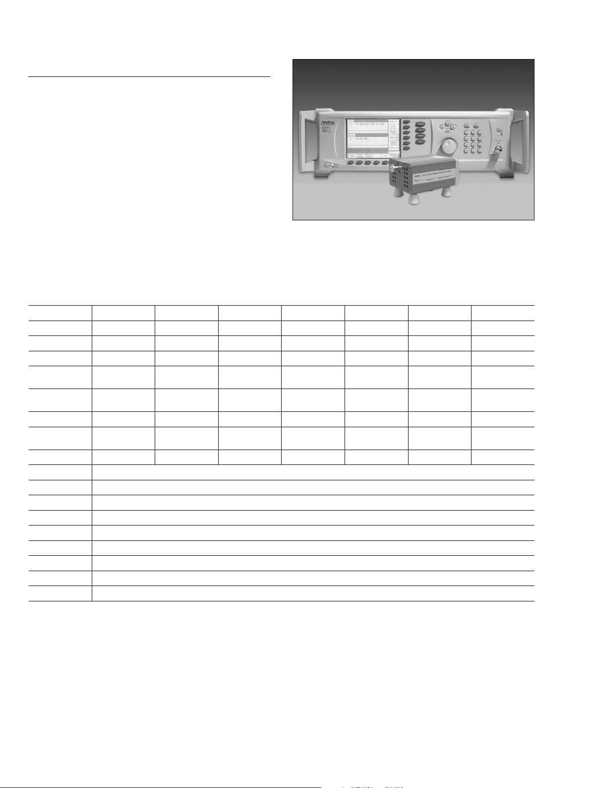
12
Millimeter Wave Multipliers
1
- 63850 series
(Option 18 recommended for DC bias.)
63850 series external, waveguide output, multipliers are available for banded frequency
coverage up to 325 GHz.
These external multipliers require at a minimum an MG3692C, with 20 GHz coverage.
The output power required to drive the modules is +10 dBm. They can be powered up
by an external power supply (+12 Vdc, 1.5A typ.) using the supplied double banana
power cord. It is recommended to purchase an MG3690C with option 18, which adds the
capability to bias these modules without the need of an additional power supply. Option 18
adds a rear panel Twinax connector that supplies the proper DC bias for these modules, and
a cable to power them up. Option 18 is not available with options 7 and 15.
63850 series multipliers have a saturated, unleveled, output power, yet their inherent
flatness is exceptional. Modulating the input drive will indeed modulate the output, except
for the case of Amplitude Modulation. Since the output is saturated, Amplitude Modulation
is not recommended with these mmW modules. Frequency and Phase Modulation is
possible, but the achieved deviation will be multiplied based on the multiplication factor of
the module. Pulse modulation is also possible, with even sharper rise and fall times than
the input. All modulation performances are not specified.
For ease of operation, the MG3690C allows the user to enter a frequency scaling factor,
the module's multiplication factor, which will be used only for purposes of displaying the
proper frequency at the output of the mmW module, on the MG3690C front panel display.
MG3690C with 63850 Series Millimeter Wave Multiplier
mmW Frequency Coverage
1
These mmW modules are produced by OML Inc. (Oleson Microwave Labs), located in Morgan Hill, CA., with mutual collaborative experiences over many years.
For detailed and up-to-date specifications, please call OML, Inc. or visit their website at www.oml-mmw.com.
2
Waveguide output flanges are per MIL.F-3922/67B-(xxx)
3
Power rolls off from –15 dBm at 200 GHz, to –25 dBm typical at 220 GHz.
4
Output power is estimated.
Multiplier p/n
1
63850-15 63850-12 63850-10 63850-08 63850-06 63850-05 63850-03
Frequency 50 GHz - 75 GHz 60 GHz - 90 GHz 75 GHz - 110 GHz 90 GHz - 140 GHz 110 GHz - 170 GHz 140 GHz - 220 GHz 220 GHz - 325 GHz
Waveguide Output WR-15 WR-12 WR-10 WR-08 WR-06 WR-05 WR-03
Flange
2
(008) (009) (010) (M08) (M06) (M05) (M03)
Output Power
(typical)
+8 dBm +6 dBm +5 dBm –5 dBm –13 dBm
–15 dBm
3
–25 dBm
4
Output Flatness
(typical) (Unleveled)
± 2 dB ± 2 dB ± 3 dB –– –– –– ––
Output Match > 12 dB > 12 dB > 12 dB > 12 dB > 12 dB > 12 dB 6 dB (typical)
Multiplication
Factor (m)
x4 x6 x6 x8 x12 x12 x18
Input Frequency 12.5 GHz - 18.75 GHz 10.0 GHz - 15.0 GHz 12.5 GHz - 18.4 GHz 11.2 GHz - 17.5 GHz 9.1 GHz - 14.2 GHz 11.6 GHz - 18.4 GHz 12.2 GHz - 18.1 GHz
Frequency Accuracy (LO Synthesizer's Accuracy x m)
Frequency Resolution (LO Synthesizer's Resolution x m)
Harmonics & Spurious –15 dBc (typical)
Input Power Required +10 dBm
RF Input Connector SMA (female)
DC Power 12 Vdc, 1.5A (double banana power cord included) Option 18 is recommended on the synthesizer, to supply the necessary bias.
Dimensions 120 mm x 110 mm x 70 mm (not including feet or interfaces)
Weight < 1 kg
Temperature +20 ºC to +30 ºC
13
Inputs and Outputs*
*Connectors may be available but not active, if option is not ordered.
** Options (7 & 18), (7 & 20), (8 & 9) are mutually exclusive, as they share the same
rear panel space.
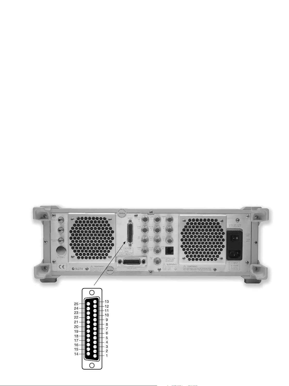
MG3690C Rear Panel
EXT ALC IN Provides for leveling the RF output signal externally with
either a detector or power meter. Signal requirements are
shown in the RF Output specifications. BNC type, rear panel.
RF OUTPUT** Provides for RF output from 50 Ω source impedance.
(Option 9) Option 9 moves the RF Output connector from the front to the
rear panel. K Connector (female) fmax ≤ 40 GHz V Connector
(female) fmax ≥ 40 GHz.
10 MHz REF IN Accepts an external 10 MHz ± 50 Hz, 0 dBm to +20 dBm
time-base signal. Automatically disconnects the internal
high-stability time-base option, if installed. 50 Ω impedance.
BNC type, rear panel.
10 MHz REF OUT Provides a 1 Vp-p, AC coupled, 10 MHz signal derived from
the internal frequency standard. 50 Ω impedance. BNC
type, rear panel.
HORIZ OUT Provides 0V at beginning and +10V at end of sweep,
(Horizontal Sweep Output) regardless of sweep width. In CW mode, the voltage is
proportional to frequency between 0V at low end and +10V at
the high end of range. In CW mode, if CW RAMP is enabled, a
repetitive, 0V to +10V ramp is provided. BNC type, rear panel.
EFC IN Provides the capability to frequency modulate the internal
crystal oscillator, allowing phase locking the synthesizer
inside an external lock loop. Specifications on page 2. BNC
type, rear panel.
AUX I/O Provides for most of the rear panel BNC connections
(Auxiliary Input/Output) through a single, 25-pin, D type connector. Supports
master-slave operation with another synthesizer or allows
for a single-cable interface with the Model 56100A Scalar
Network Analyzer and other Anritsu instruments (see figure
below). 25 pin D-type, rear panel.
SERIAL I/O Provides access to RS-232 terminal ports to support
service and calibration functions and master-slave
operations. RJ45 type, rear panel.
IEEE-488 GPIB Provides input/output connections for the General Purpose
Interface Bus (GPIB). Type 57, rear panel.
mmW BIAS** Provides the bias for the external waveguide multipliers for
(Option 18) coverage up to 325 GHz. Twinax, rear panel.
RF, LO, IF** Provides access to an internal IF up-conversion mixer.
(Option 7) K Connector (female) 3X, rear panel.
PULSE TRIG IN Accepts an external TTL compatible signal to pulse
(Option 26) modulate the RF output signal or to trigger or to gate the
optional internal pulse generator. BNC type, rear panel.
PULSE SYNC OUT Provides a TTL compatible signal, synchronized to the
(Option 27) internal pulse modulation output. BNC type, rear panel.
PULSE VIDEO OUT Provides a video modulating signal from the internal pulse
(Option 27) generator. BNC type, rear panel.
AM IN Accepts an external signal to amplitude modulate the
(Option 14) RF output signal, 50 Ω impedance. BNC type, rear panel.
FM/ΦM IN Accepts an external signal to frequency or phase modulate
(Option 12) the RF output signal. 50 Ω impedance. BNC type, rear panel.
AM OUT Provides the amplitude modulation waveform from the
(Option 27) internal LF generator. BNC type, rear panel.
FM/ΦM OUT Provides the frequency or phase modulation waveform from
(Option 27) the internal LF generator. BNC type, rear panel.
SCAN MOD IN** Accepts an external signal to scan modulate the RF output
(Option 20) signal. High Impedance. BNC type, rear panel.
POWER MONITOR IN Accepts an external detector for power monitoring. Custom
(Option 8) type, rear panel.
Aux I/O pins:
1. Horizontal Output
2. Chassis Ground
3. Sequential Sync Output
4. Low Alternate Enable Output
5. Marker Output
6. Retrace Blanking Output
7. Low Alternate Sweep Output
8. Chassis Ground
9. -
10. Sweep Dwell Output
11. Lock Status Output
12. Penlift
13. External Trigger Input
14. V/GHz Output
15. End-of-Sweep Input
16. End-of-Sweep Output
17. -
18. Sweep Dwell Input
19. -
20. Bandswitch Blanking Output
21. Master Reset
22. Horizontal Sweep Input
23. Horizontal Sweep Input Return
24. Chassis Ground
25. Memory Sequencing Input