Anritsu_MG3692C.PDF - 第7页
7 Maximum Leveled Output Power With Option 15 (High Power) Installed***: Minimum Settable Power Without an Attenuator: –20 dBm With an Attenuator : –120 dBm Minimum Leveled Output Power Without an Attenuator: –15 dBm (–2…
6
RF Output
Power level specifications apply at 25 ± 10 ºC.
Maximum Leveled Output Power***:
* ≤ 2.2 GHz with Option 4
** > 2.2 GHz with Option 4
*** For output power with Option 22, 0.1 Hz to 10 MHz coverage, derate all specifications by 2 dB
**** Typical 60 GHz to 67 GHz
Model Number Configuration
Frequency Range
(GHz)
Output Power
(dBm)
Output Power With Step
Attenuator (dBm)
Output Power With Electronic
Step Attenuator (dBm)
MG3691C
w/opt 4 or 5
STD
< 2 GHz*
≥ 2 GHz** to ≤ 10 GHz
+19.0
+19.0
+18.0
+18.0
+15.0
+13.0
MG3692C
w/opt 4 or 5
STD
STD
< 2 GHz*
≥ 2 GHz** to ≤ 10 GHz
> 10 GHz to ≤ 20 GHz
+19.0
+19.0
+17.0
+18.0
+18.0
+15.0
Not Available
MG3693C
w/opt 4 or 5
STD
STD
STD
< 2 GHz*
≥ 2 GHz** to ≤ 10 GHz
> 10 GHz to ≤ 20 GHz
> 20 GHz to ≤ 31.8 GHz
+15.0
+15.0
+12.0
+9.0
+14.0
+14.0
+10.0
+6.0
Not Available
MG3694C
w/opt 4 or 5
STD
STD
STD
< 2 GHz*
≥ 2 GHz** to ≤ 10 GHz
> 10 GHz to ≤ 20 GHz
> 20 GHz to ≤ 40 GHz
+15.0
+15.0
+12.0
+9.0
+14.0
+14.0
+10.0
+6.0
Not Available
MG3695C
w/opt 4 or 5
STD
STD
STD
< 2 GHz*
≥ 2 GHz** to ≤ 20 GHz
> 20 GHz to ≤ 40 GHz
> 40 GHz to ≤ 50 GHz
+12.0
+10.0
+6.0
+3.0
+10.0
+8.0
+3.0
+0.0
Not Available
MG3697C
w/opt 4 or 5
STD
STD
STD
< 2 GHz*
≥ 2 GHz** to ≤ 20 GHz
> 20 GHz to ≤ 40 GHz
> 40 GHz to ≤ 67 GHz
+12.0
+10.0
+6.0
+3.0
+10.0
+8.0
+3.0
+0.0****
Not Available
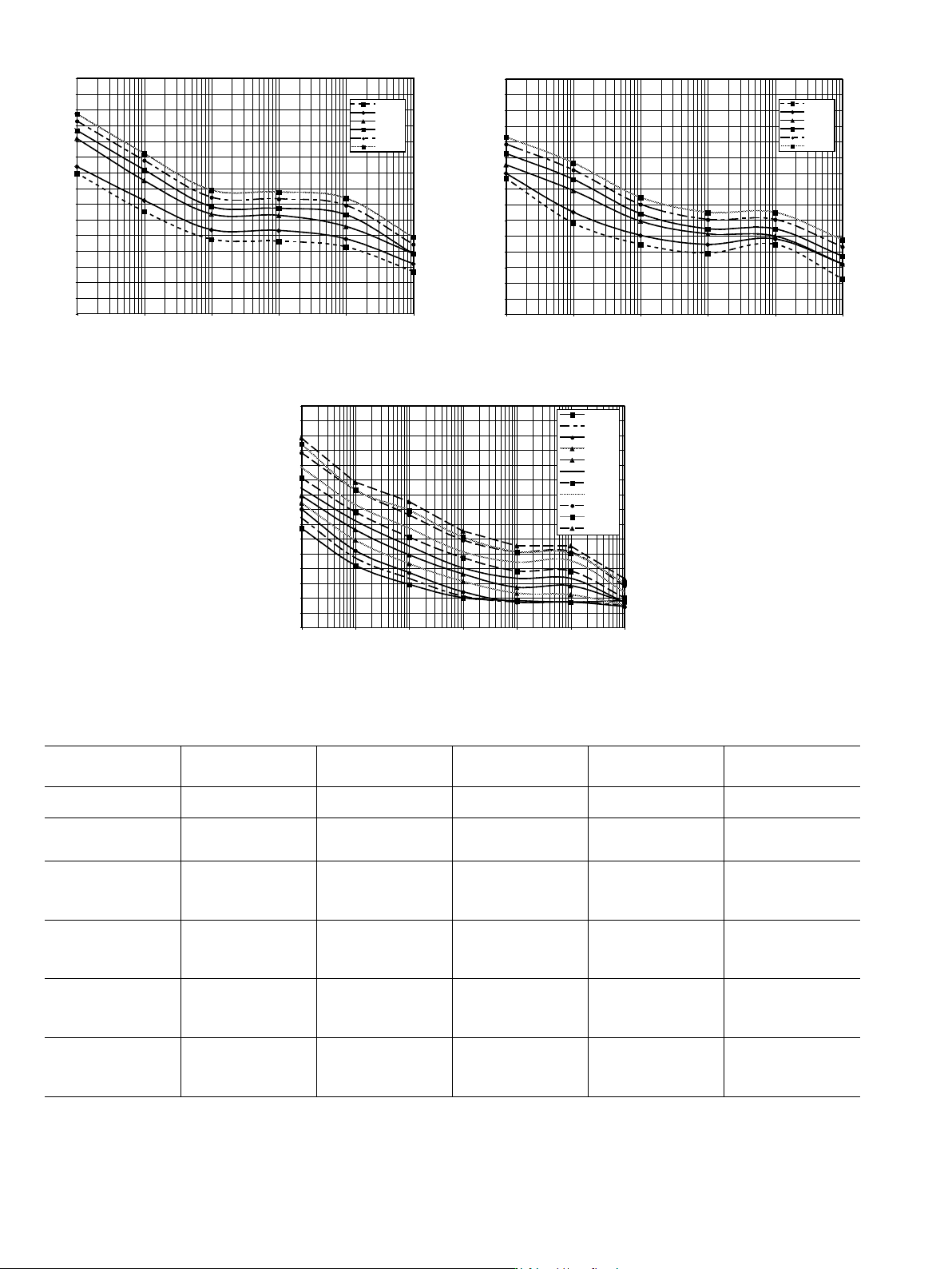
Measured SSB Phase Noise MG3690C with Options 3 & 4
-170
-160
-150
-140
-130
-120
-110
-100
-90
-80
-70
-60
-50
-40
-30
-20
10 100 1000 10000 100000 1000000
Offset (Hz)
L(f) (dBc/Hz)
1 GHz
2 GHz
10 GHz
20 GHz
40 GHz
67 GHz
Measured SSB Phase Noise MG3690C with Option 4
-170
-160
-150
-140
-130
-120
-110
-100
-90
-80
-70
-60
-50
-40
-30
-20
10 100 1000 10000 100000 1000000
Offset (Hz)
1 GHz
2 GHz
10 GHz
20 GHz
40 GHz
67 GHz
L(f) (dBc/Hz)
-170
-160
-150
-140
-130
-120
-110
-100
-90
-80
-70
-60
-50
-40
-30
-20
1 10 100 1000 10000 100000 1000000
15 MHz
30 MHz
60 MHz
120 MHz
250 MHz
500 MHz
1 GHz
2 GHz
6 GHz
10 GHz
20 GHz
Measured SSB Phase Noise
MG3690C with Options 3X and 4
Offset (Hz)
L(f) (dBc/Hz)
7
Maximum Leveled Output Power With Option 15 (High Power) Installed***:
Minimum Settable Power
Without an Attenuator: –20 dBm
With an Attenuator: –120 dBm
Minimum Leveled Output Power
Without an Attenuator: –15 dBm (–20 dBm, typical)
With an Attenuator: –115 dBm (MG3691C, MG3692C, MG3693C, and MG3694C)
–105 dBm (MG3695C, and MG3697C)
With an Electronic Attenuator: –125 dBm (MG3691C)
Unleveled Output Power Range (typical)
Without an Attenuator: > 40 dB below max power.
With an Attenuator: > 130 dB below max power.
Power Level Switching Time (to within specified accuracy)
Without Change in Step Attenuator: < 3 ms typical
With Change in Step Attenuator: < 20 ms typical
With Change in Electronic Step Attenuator: < 3 ms typical. Power level changes
across –70 dB step will result in 20 ms delay.
Step Attenuator (Option 2)
Adds a 10 dB/step attenuator, with 110 dB range on models ≤ 40 GHz, and 90 dB range
on models > 40 GHz. Option 2E adds an electronic version with 120 dB range, only
available on an MG3691C. Option 2E is not available on units with Option 22, coverage
down to 0.1 Hz.
Model Number Configuration
Frequency Range
(GHz)
Output Power
(dBm)
Output Power
With Step
Attenuator (dBm)
Output Power
With Electronic
Step Attenuator (dBm)
MG3691C
w/opt 4 or 5
< 2 GHz*
≥ 2 GHz** to ≤ 10 GHz
+19.0
+25.0
+18.0
+24.0
+15.0
+16.0
w/o opt 4 or 5 ≥ 2 GHz to ≤ 10 GHz +26.0 +25.0 +16.0
MG3692C
w/opt 4 or 5
< 2 GHz*
2 GHz to 10 GHz
> 10 GHz to 16 GHz
> 16 GHz to 20 GHz
+19 dBm
+25 dBm
+22 dBm
+21 dBm
+18 dBm
+24 dBm
+20 dBm
+19 dBm
Not Available
w/o opt 4 or 5
2 GHz to 10 GHz
> 10 GHz to 16 GHz
> 16 GHz to 20 GHz
+26 dBm
+25 dBm
+23 dBm
+25 dBm
+23 dBm
+21 dBm
MG3693C
w/opt 4 or 5
< 2 GHz*
≥ 2 GHz** to ≤ 20 GHz
> 20 GHz to ≤ 3 GHz
+17.0
+21.0
+17.0
+16.0
+19.0
+15.0
Not Available
w/o opt 4 or 5
≥ 2 GHz to ≤ 20 GHz
> 20 GHz to ≤ 31.8 GHz
+23.0
+19.0
+21.0
+17.0
MG3694C
w/opt 4 or 5
< 2 GHz*
≥ 2 GHz** to ≤ 20 GHz
> 20 GHz to ≤ 40 GHz
+17.0
+21.0
+17.0
+16.0
+19.0
+15.0
Not Available
w/o opt 4 or 5
≥ 2 GHz to ≤ 20 GHz
> 20 GHz to ≤ 40 GHz
+23.0
+19.0
+21.0
+17.0
MG3695C
w/opt 4 or 5
< 2 GHz*
≥ 2 GHz** to ≤ 20 GHz
> 20 GHz to ≤ 40 GHz
> 40 GHz to ≤ 50 GHz
+16
+21
+17
+11
+14
+19
+15
+8
Not Available
w/o opt 4 or 5
≥ 2 GHz to ≤ 20 GHz
> 20 GHz to ≤ 40 GHz
> 40 GHz to ≤ 50 GHz
+23
+19
+13
+21
+17
+10
MG3697C
w/opt 4 or 5
< 2 GHz*
≥ 2 GHz** to ≤ 20 GHz
> 20 GHz to ≤ 40 GHz
> 40 GHz to ≤ 67 GHz
> 67 GHz to ≤ 70 GHz
+16
+19
+16
+9
+3*****
+15
+18
+14
+6****
0*****
Not Available
w/o opt 4 or 5
≥ 2 GHz to ≤ 20 GHz
> 20 GHz to ≤ 40 GHz
> 40 GHz to ≤ 67 GHz
> 67 GHz to ≤ 70 GHz
+21
+19
+9
+3*****
+19
+16
+6****
0*****
* ≤ 2.2 GHz with Option 4
** > 2.2 GHz with Option 4
*** For output power with Option 22, 0.1 Hz to 10 MHz coverage, derate all specifications by 2 dB
**** Typical 60 GHz to 67 GHz
***** Typical
Analog Sweep Mode (typical):
32
30
28
26
24
22
20
18
16
0510 15 20 25 30 35 40
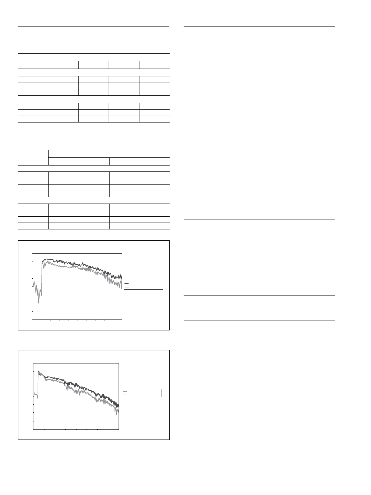
MG3694C, 40 GHz
with High Power Option 15
Maximum Leveled Output Power (Typical)
Output Power Level (dBm)
Frequency (GHz)
Low End Frequency Coverage:
Options 2 and/or 22
further reduce power.
Check the MG3695C
power plot for typical
step attenuator loss.
2 GHz Only, No Options 4 or 5
10 MHz, with Option 4 or 5
32
30
28
26
24
22
20
18
16
02468101214161820
MG3692C, 20 GHz
with High Power Option 15
Maximum Leveled Output Power (Typical)
Output Power Level (dBm)
Frequency (GHz)
Low End Frequency Coverage:
2 GHz Only, No Options 4 or 5
10 MHz, with Option 4 or 5
Options 2 and/or 22
further reduce power.
Check the MG3695C
power plot for typical
step attenuator loss.
Typical MG3694C maximum available output power
*Typical
**Accuracy and Flatness with high power Option 15, is ±1.5 dB. It is also ±1.5 dB below
20 MHz, with or without Option 15.
Typical MG3692C maximum available output power
Other Output Power Specifications
Output Units: Output units selectable as either dBm or mV. Selection of mV
assumes 50 Ω
load. All data entry and display are in the selected units.
Output Power Resolution: 0.01 dB or 0.001 mV
Source Impedance: 50 Ω nominal
Source SWR (Internal Leveling): < 2.0 typical
Power Level Stability with Temperature: 0.04 dB/deg C typical
Level Offset: Offsets the displayed power level to establish a new reference level.
Output On/Off: Toggles the RF output between an Off and On state. During the Off
state, the RF oscillator is turned off. The On or Off state is indicated by two LEDs
located below the OUTPUT ON/OFF key on the front panel.
RF On/Off Between Frequency Steps: System menu selection of RF On or RF Off
during frequency switching in CW, Step Sweep, and List Sweep modes.
RF On/Off During Retrace: System menu selection of RF On or RF Off
during retrace.
Internal Leveling: Power is leveled at the output connector in all modes.
External Leveling:
External Detector: Levels output power at a remote detector location. Accepts a
positive or negative 0.5 mV to 500 mV input signal from the remote detector. L1
adjusts the input signal range to an optimum value. BNC connector, rear panel.
External Power Meter: Levels output power at a remote power meter location.
Accepts a ± 1 V full scale input signal from the remote power meter. L1 adjusts
the input signal range to an optimum value. BNC connector, rear panel.
External Leveling Bandwidth: 30 kHz typical in Detector mode. 0.7 Hz typical in
Power Meter mode.
User Level Flatness Correction:
Number of points: 2 to 801 points per table
Number of tables: 5 available
Entry modes: GPIB power meter or computed data
CW Power Sweep
Range: Sweeps between any two power levels at a single CW frequency.
Resolution: 0.01 dB/step (Log) or 0.001 mV (Linear)
Accuracy: Same as CW power accuracy.
Log/Linear Sweep: Power sweep selectable as either log or linear.
Log sweep is in dB; linear sweep is in mV.
Step Size: User-controlled, 0.01 dB (Log) or 0.001 mV (Linear)
to the full power range of the instrument.
Step Dwell Time: Variable from 1 ms to 99 seconds. If the sweep crosses a step
attenuator setting, there will be a sweep dwell of approximately 20 ms to allow
setting of the step attenuator.
Sweep Frequency/Step Power
A power level step occurs after each frequency sweep. Power level remains
constant for the length of time required to complete each sweep.
Internal Power Monitor (Option 8)
Sensors: Compatible with Anritsu 560-7, 5400-71, or 6400-71 series detectors.
Rear panel input.
Range: +16 dBm to –35 dBm
Accuracy: ± 1 dBm, (+16 dBm to –10 dBm)
± 2 dBm, (–10 dBm to –35 dBm)
Resolution: 0.1 dBm minimum
Accuracy and Flatness
Accuracy specifies the total worst case accuracy. Flatness is included within the
accuracy specification.
Step Sweep and CW Modes:
Attenuation
Below
Max Power
Frequency (GHz)
≤ 40** 40-50 50-60 60-67
Accuracy:
0 dB - 25 dB ± 1.0 dB ± 1.5 dB ± 1.5 dB ± 1.5 dB
25 dB - 60 dB ± 1.0 dB ± 1.5 dB ± 3.5 dB* N/A
60 dB - 100 dB ± 1.0 dB ± 2.5 dB* ± 3.5 dB* N/A
Flatness:
0 dB - 25 dB ± 0.8 dB ± 1.1 dB ± 1.1 dB ± 1.1 dB
25 dB - 60 dB ± 0.8 dB ± 1.1 dB ± 3.1 dB* N/A
60 dB - 100 dB ± 0.8 dB ± 2.1 dB* ± 3.1 dB* N/A
Attenuation
Below
Max Power
Frequency (GHz)
0.01-0.05 0.05-20 20-40 40-67
Accuracy:
0 dB - 12 dB ± 2.0 dB ± 2.0 dB ± 2.0 dB ± 3.0 dB
12 dB - 30 dB ± 3.5 dB ± 3.5 dB ± 4.6 dB ± 5.6 dB
30 dB - 60 dB ± 4.0 dB ± 4.0 dB ± 5.2 dB ± 6.2 dB
60 dB - 122 dB ± 5.0 dB ± 5.0 dB ± 6.2 dB ± 7.2 dB
Flatness:
0 dB - 12 dB ± 2.0 dB ± 2.0 dB ± 2.0 dB ± 2.5 dB
12 dB - 30 dB ± 3.5 dB ± 3.5 dB ± 4.1 dB ± 5.1 dB
30 dB - 60 dB ± 4.0 dB ± 4.0 dB ± 4.6 dB ± 5.6 dB
60 dB - 122 dB ± 5.0 dB ± 5.0 dB ± 5.2 dB ± 6.2 dB
8